
F-4 Phantom II
Bits and pieces
F-4 Phantom II
Bits and pieces
This page will be my attempt to illustrate a few details of the F-4 and try and highlight some of the differences between models. It will in no way be an in depth effort.
 |
 |
 |
 |
 |
|
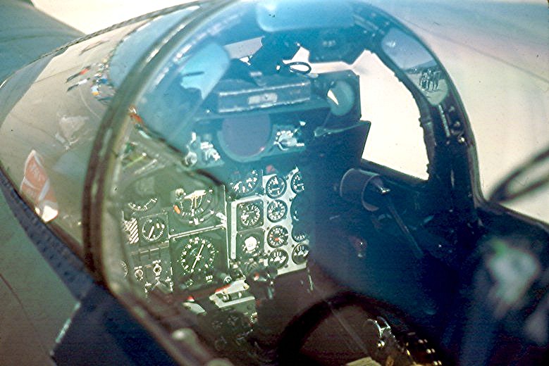
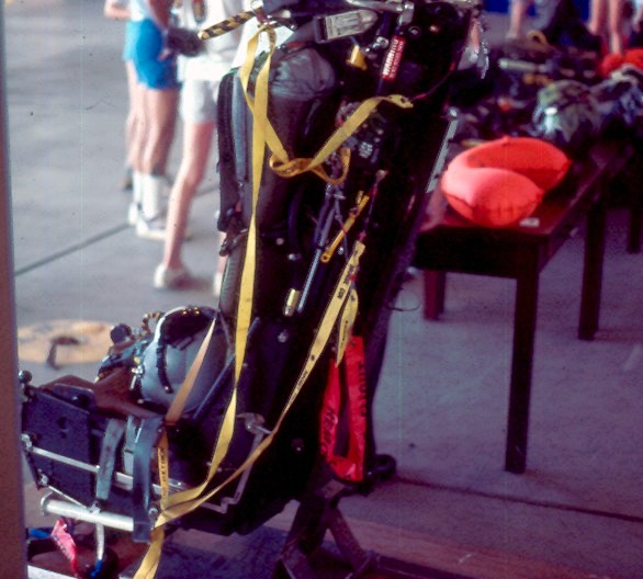
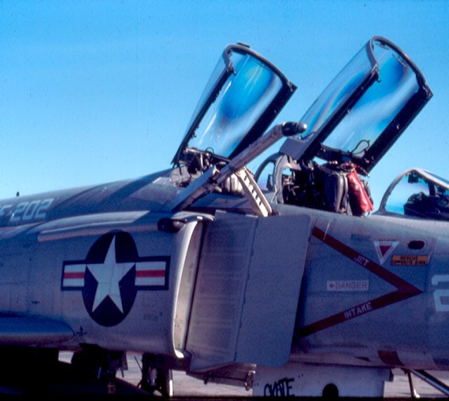
Seats
 |

|
All F-4s used versions of the
Martin Baker ejection seat. (CB)
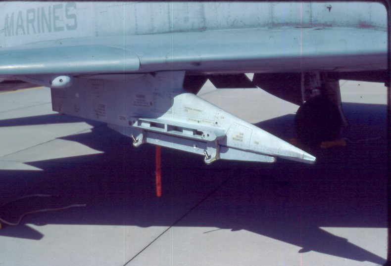
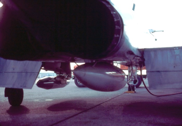
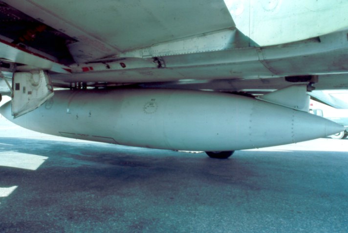
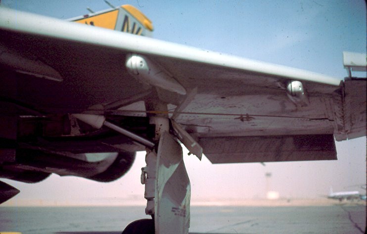
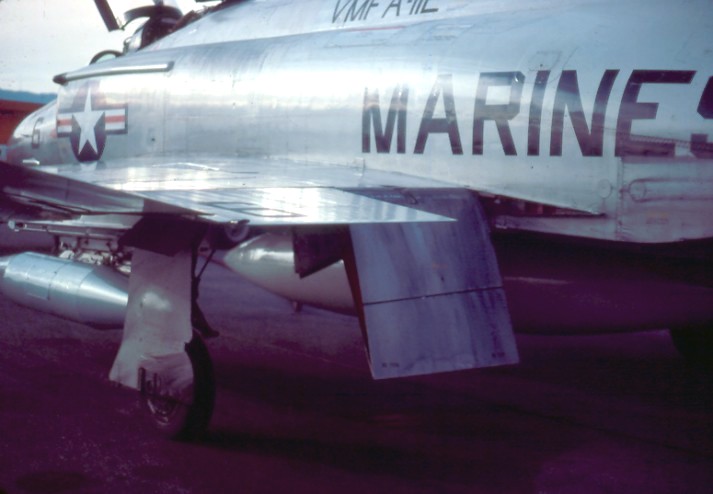
Pylons and fuel tanks
 |
 |
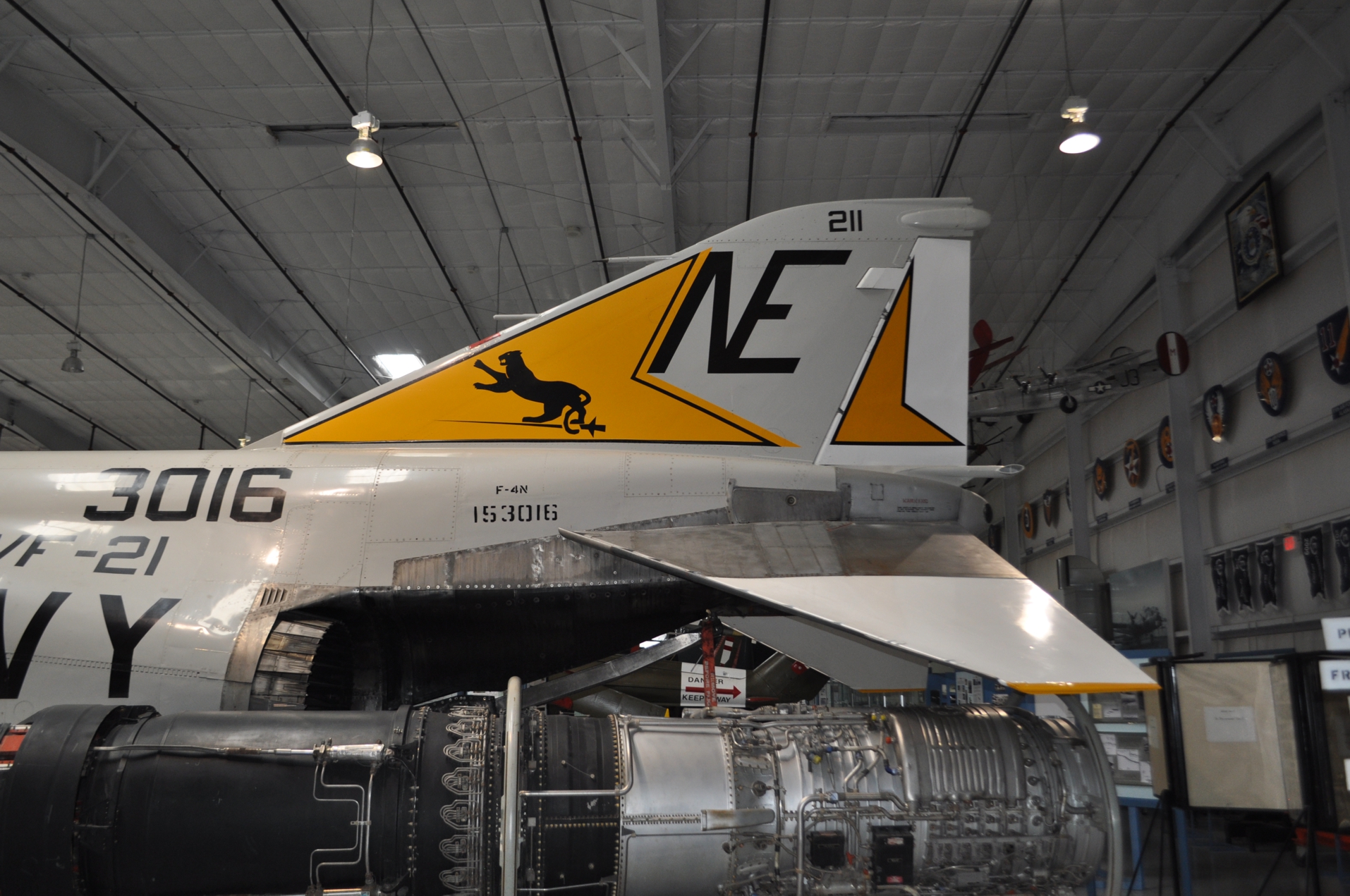
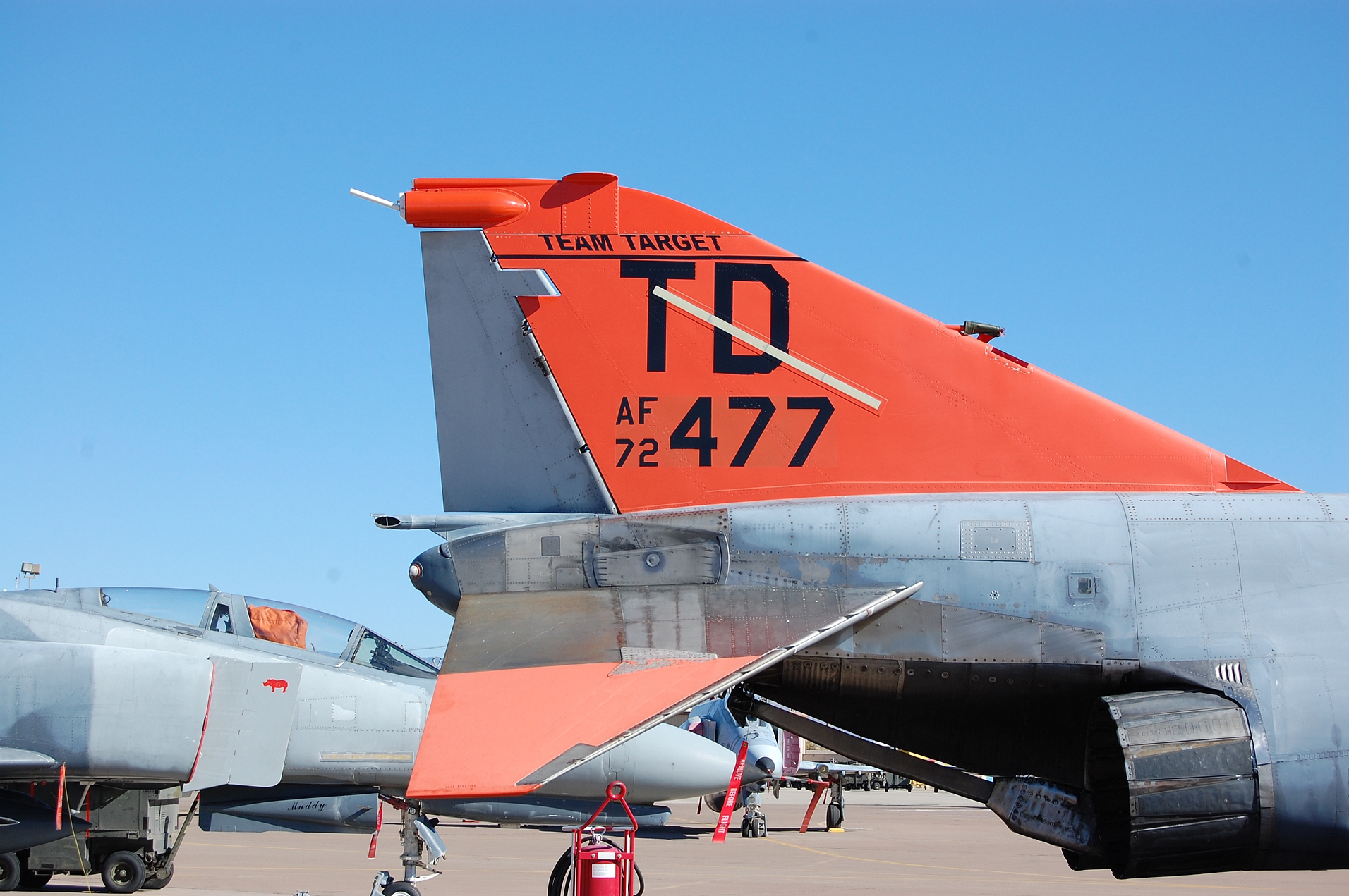
Two
different types of inboard pylons were used: A
straight, pointed (triangular) pylon for Navy F-4s
(left) and a rounded one on Air Force aircraft (right).
(CB)
 |
 |
 |
The F-4 usually carried 600
gallon tanks on the center pylon and 370 gallon tanks on
the outboard wing pylons. The photo on the left is
of the first type of tank carried by USN, USMC and most
USAF F-4s. The second one is of an tank looking
similar to an F-15 tank later carried on USAF aircraft.
The photo on the right shows the 370 gallon wing
tanks. (CB)
 |
 |
 |
 |
 |
 |
 |
 |
 |
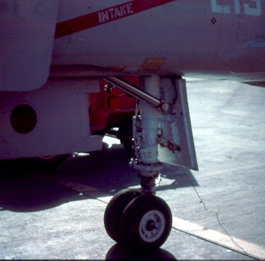
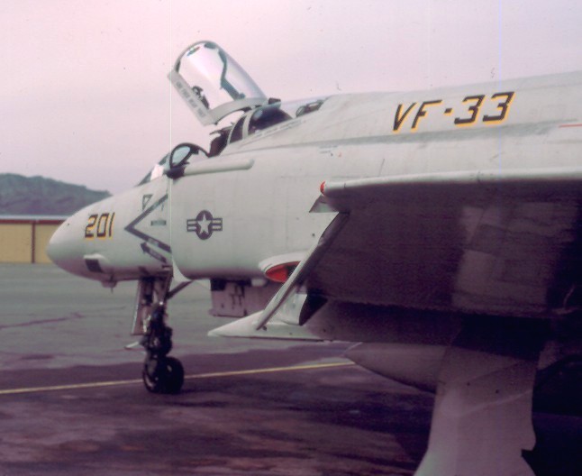
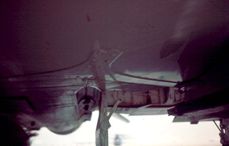
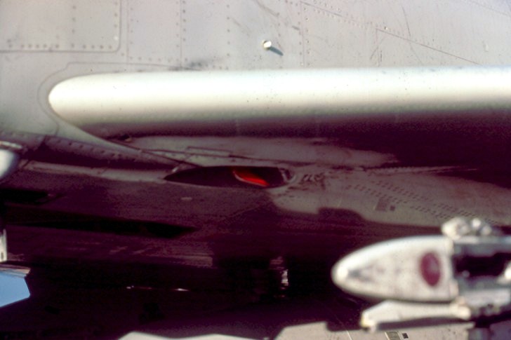
Navy refueling is via "probe and
drogue", using a probe on the receiving aircraft to engage
a drogue (or basket) reeled out from the tanker. The
Navy F-4 accomplished this using a retractable
refueling probe on the starboard side of the aircraft
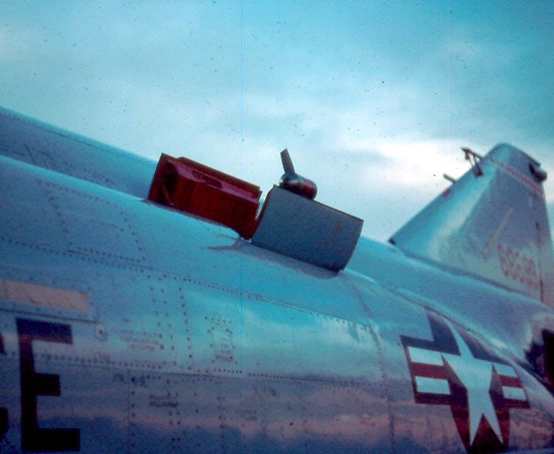
(left). The Air Force uses
a "flying boom" that is guided by a boom operator aboard
the tanker. The boom is actually flown close to
the aircraft and a retractable probe is inserted into a
receptacle on the spine of the F-4 (center). A
third type of refueling is accomplished with an add on
unit that consists of a fixed probe attached to the
right side of the F-4, with plumbing running up the
right side of the aircraft and into the Air Force
receptacle (right). The aircraft in the photo was
operated by Flight Systems inc., and was modified to be
able to operate and refuel with Navy needs. This
system is also used by the Israeli Air Force. (CB)
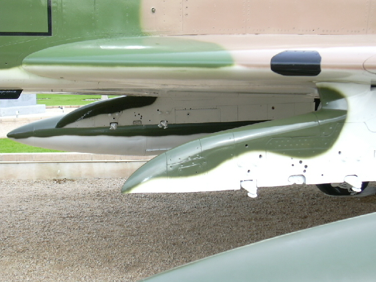
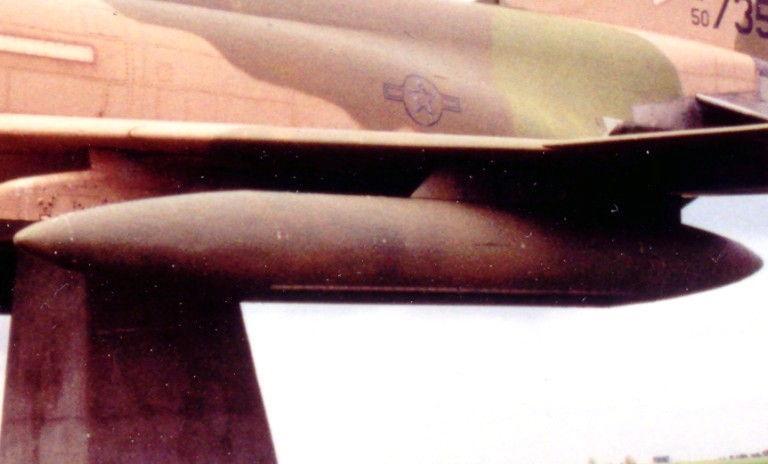
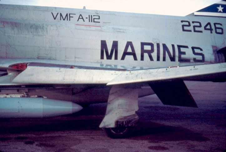
Stabilizers
 |
 |
 |
 |
 |
 |
 |
 |
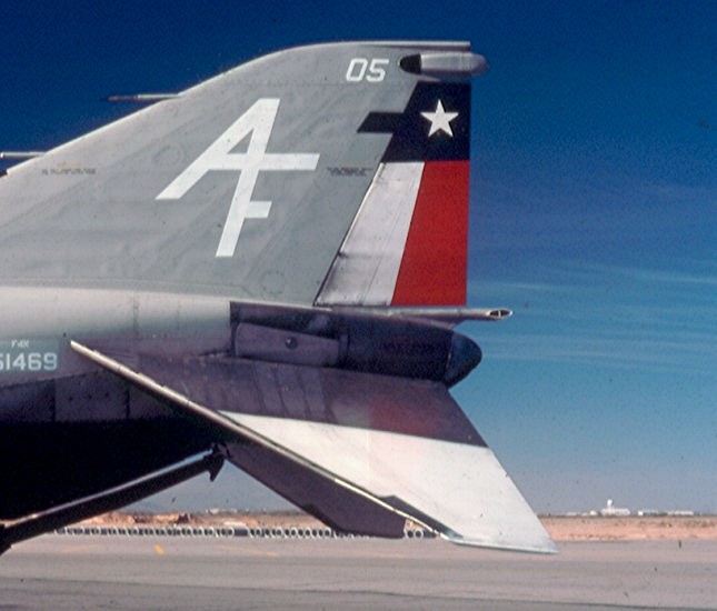
F-4s were initially
produced with a stabilizer having a smooth leading edge,
or "un-slotted" as illustrated by the F-4F to the left.
This also lacks the "fish plate" reinforcement common to
Air Force F-4s. This type was used on F-4B, early
RF-4B, F-4F and F-4M (Phantom FGR.2) Phantoms.
(CB)
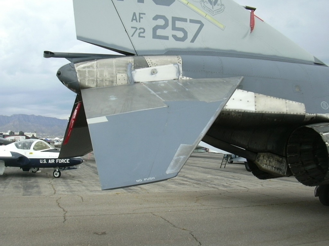
The second photo of a Spanish AF F-4C
shows an "un-slotted" stab with the "fish plate". This
was the standard for F-4C, F-4D and RF-4C Phantoms in
Air Force service. (CB)
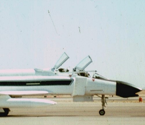
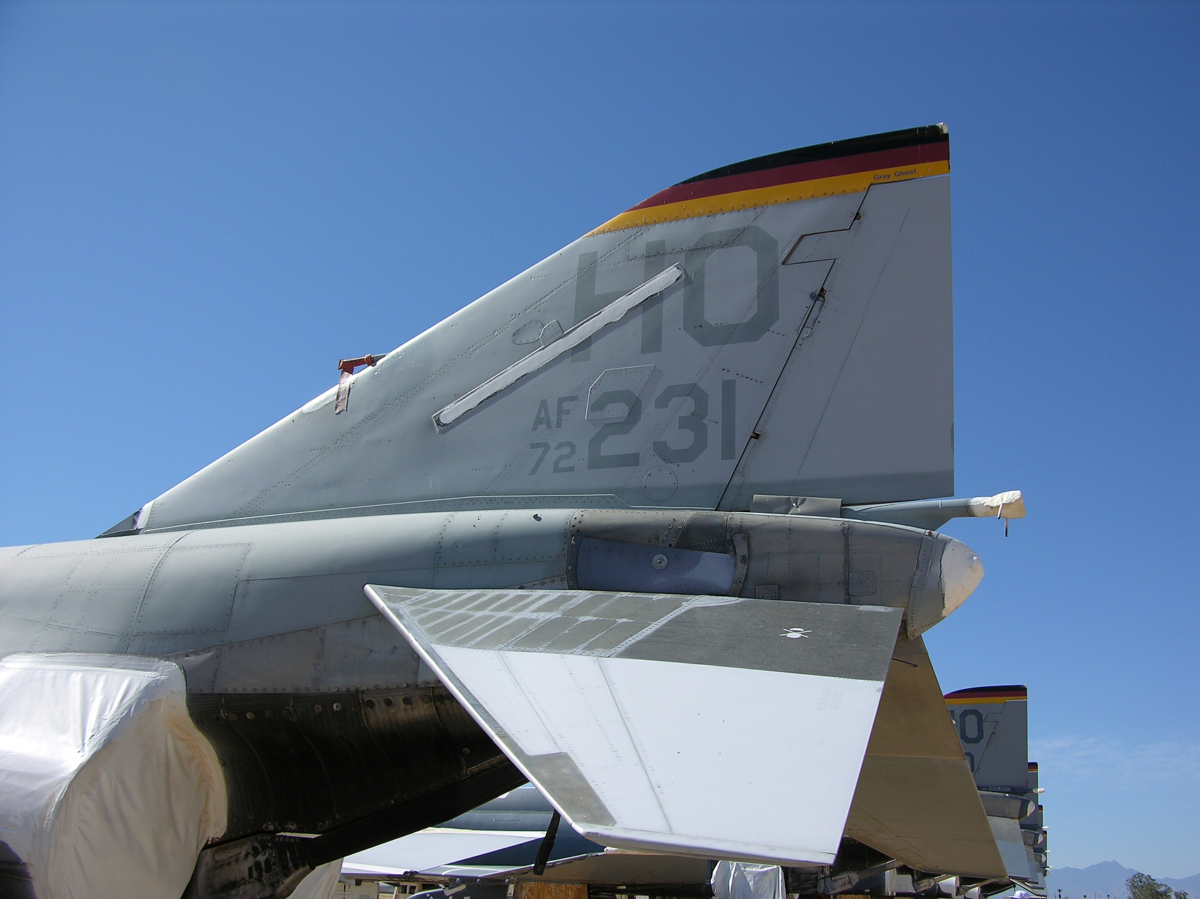
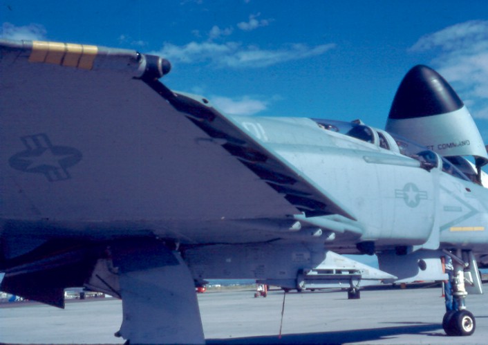
The third photo
illustrates the "slotted" stabilizer fitted to some
F-4B, all F-4N, F-4J, F-4S and F-4K (Phantom FG.1)
Phantoms. (CB)
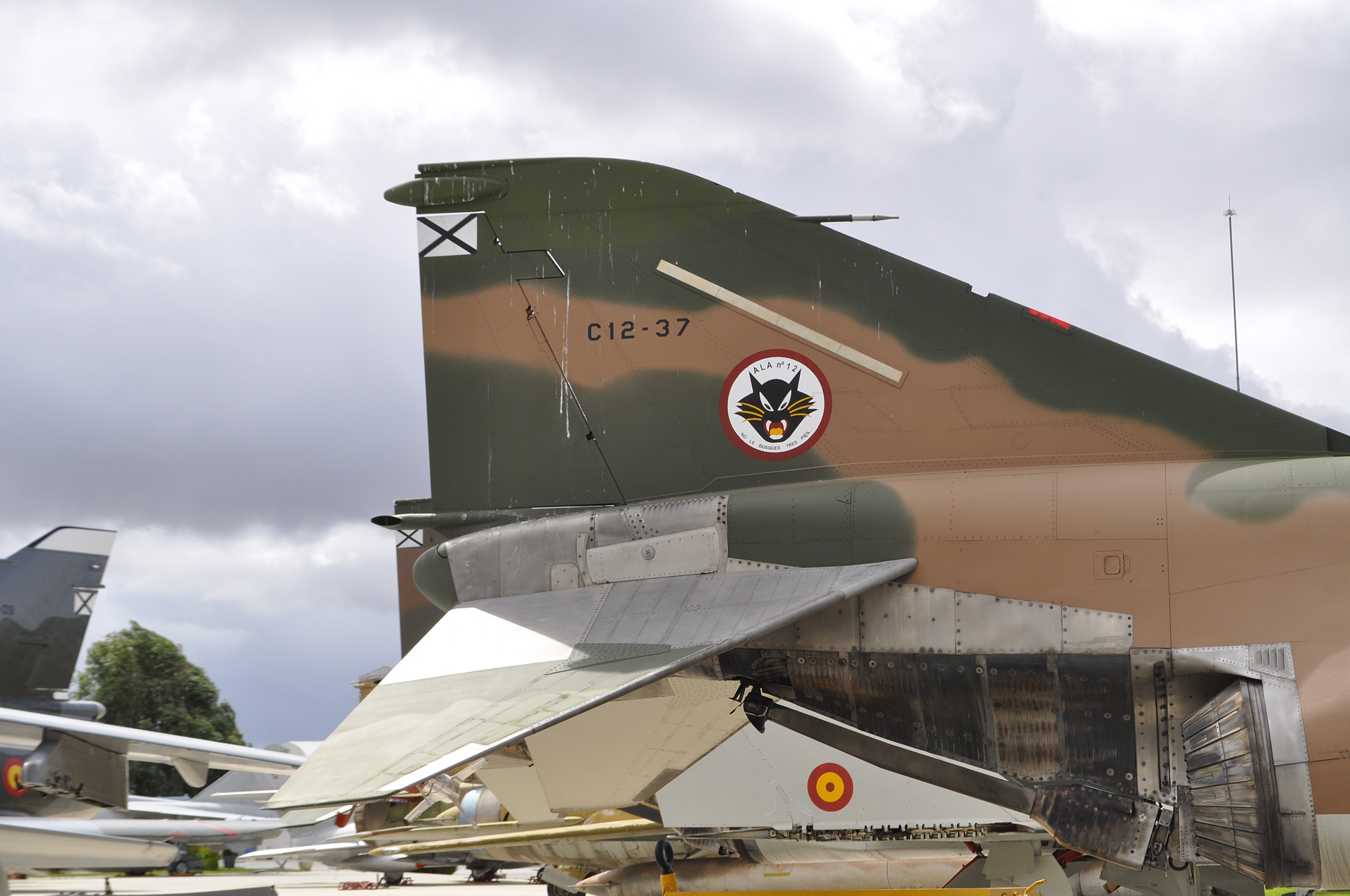
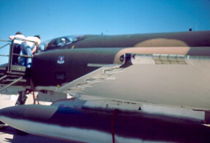
The final photo
illustrates the "slotted" stabilizer with "fish plate"
as used on F-4E and F-4G Phantoms. (CB)
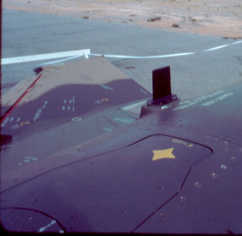
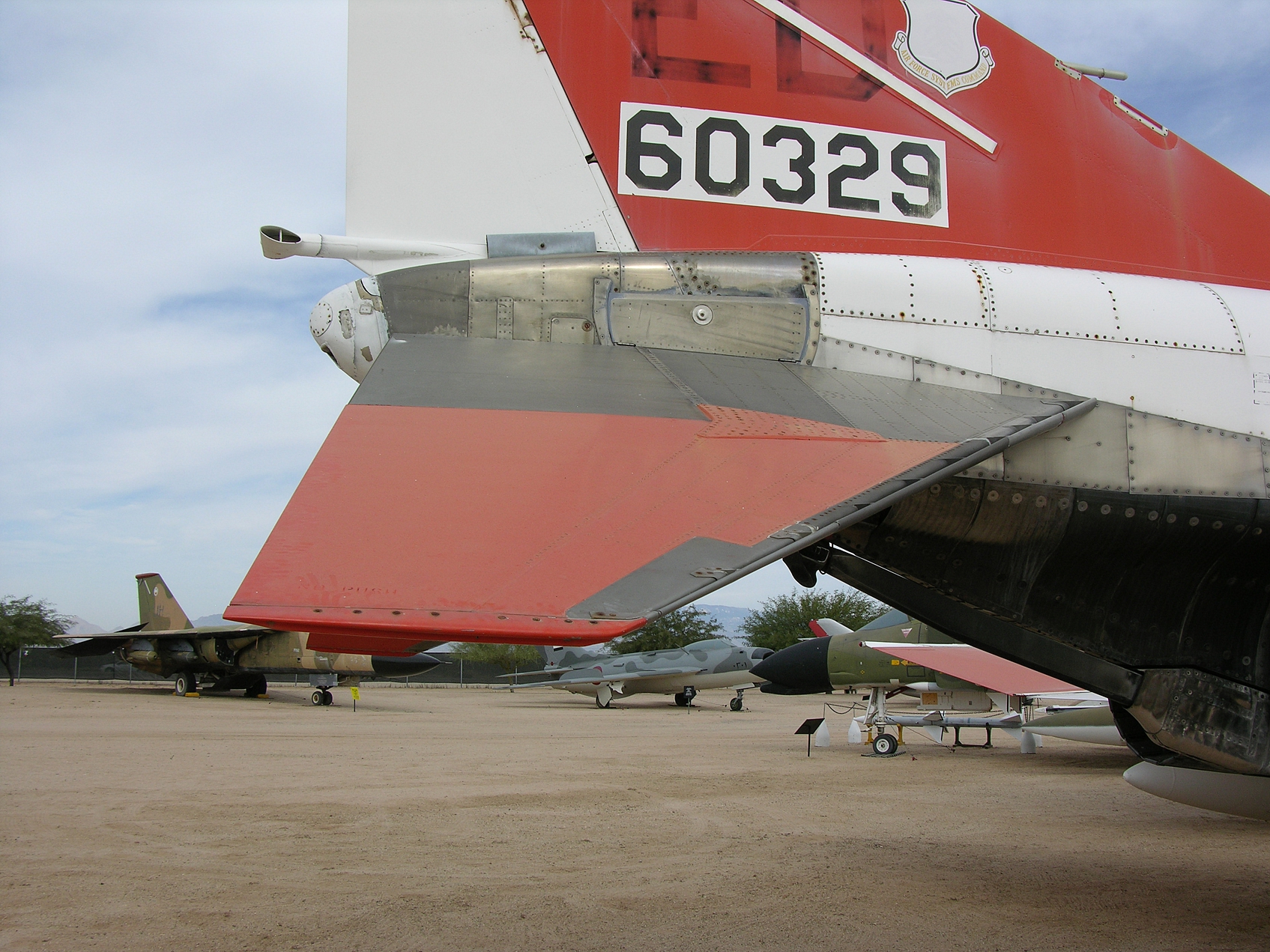
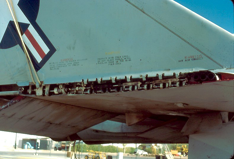
"Slotted" stabilizers were fitted to
most U.S. F-4s. The photo to the left shows the
slot fairly well. The aircraft is an F-4N, the
dents and dings on the leading edge are from the
catapult bridle rebounding from the flight deck and
striking the aircraft during launch. The was quite
common on USN F-4s. The next photo is also of the
stabilizer on an F-4N. The next to last is an F-4E
and the final one is of a German AF F-4F. Note the
"fish plate" between the bare metal portion and the
painted portion. This was unique to USAF F-4s and
GAF F-4F. (CB)
 |
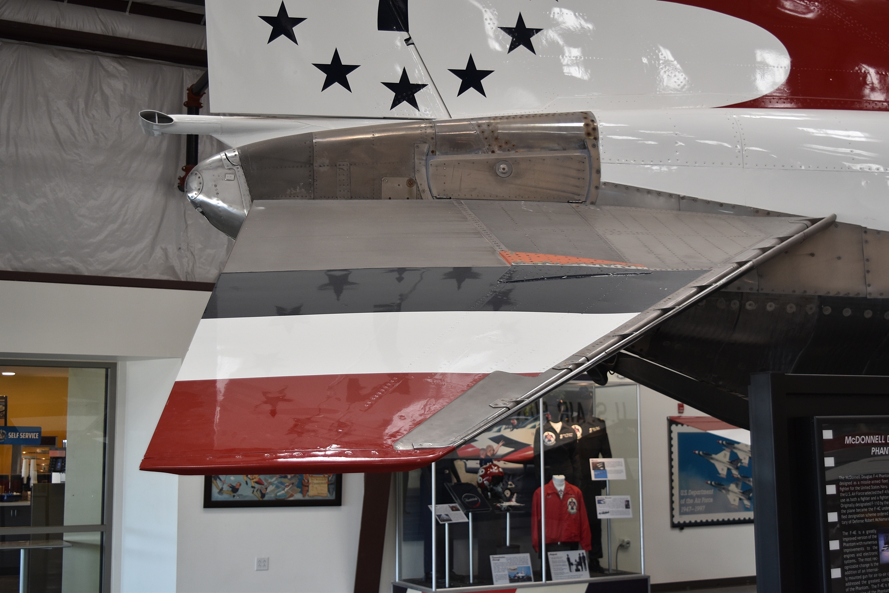 |
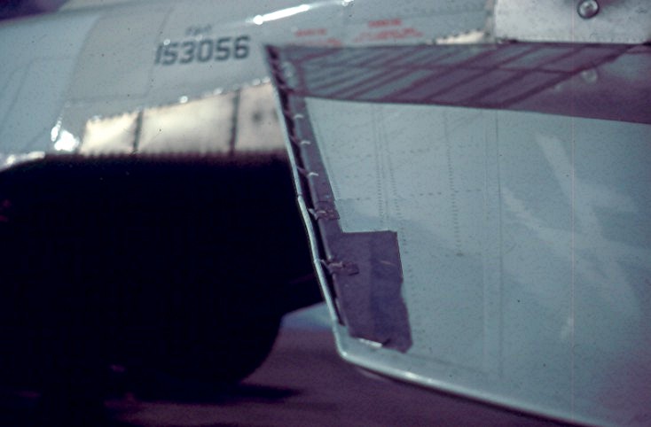
A better view of the
slots in the leading edge of the stabilizer. (CB)
 |
 |
 |
 |
 |
 |
 |
 |
 |
 |
 |
 |
 |
 |
 |
 |
 |
 |
|
 |
 |
 |
 |
 |
To return to:
Please send me your comments and suggestions;

Page
created 05-31-03
Modified 11-30-21