Grumman F4F and FM Wildcat details
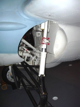
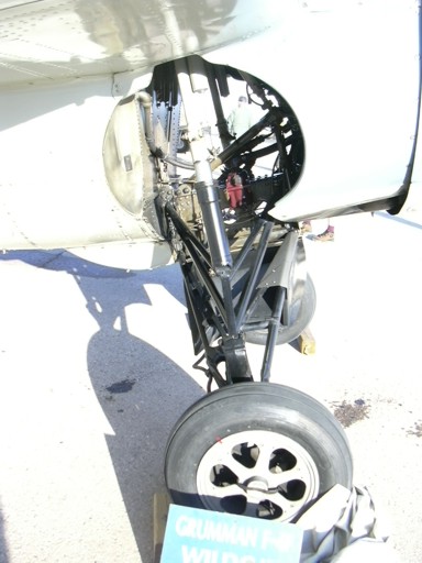
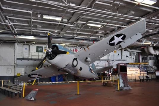
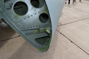
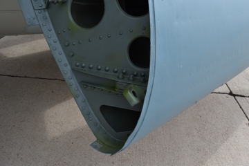
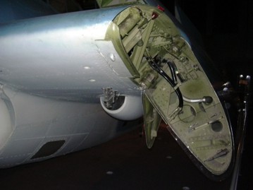
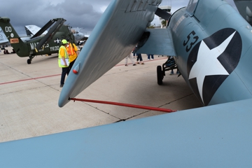
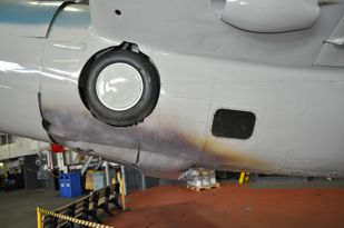
Wildcat landing gear
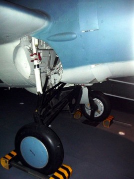
The
Wildcat landing
gear was the same
for all
models. The
above photos are of
an FM-1, FM-2
and F4F-4. The
inside of the gear
well is light gray,
the gear itself is
also light gray
above the pivot
point of the
"trapeze".
The portion below
that is a heat
resistant flat
black, this is due
to that portion's
exposure to engine
exhaust when the
landing gear is
lowered. (CB)
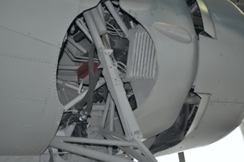
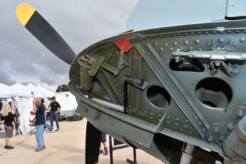
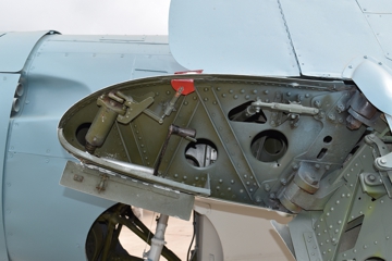
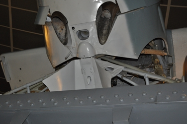
The
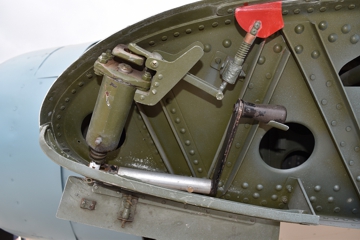
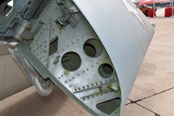
wheel well as seen on the O'Hare airport wildcat. The
first photo is looking aft and showing bulkhead forward of
the cockpit. The "bicycle chain" that raises and
lowers the landing gear is visible against that
bulkhead. The second photo is looking forward and
the supercharger intercoolers are prominent inside the
opening.
The intercooler is tilted outboard at the top and the
upper edge protrudes from the fuselage creating the need
for the "blister" on the outside. The red box
visible inside the wheel well is storage for the star
cartridges employed with the Coffman starter. Often
referred to as a "shotgun starter" the starter was driven
by expanding gas from a cartridge detonated inside
achamber. For a good description follow the link to
Wikipedia.
(CB)
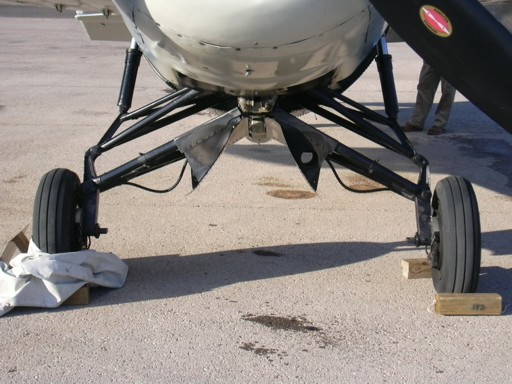
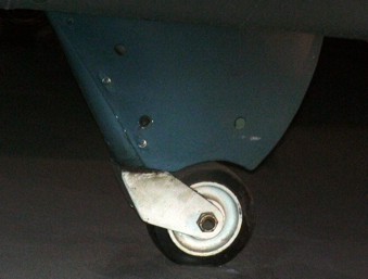
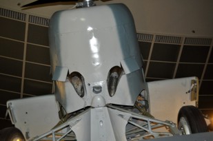
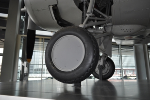
The two tail wheel photos on the left
show the hard rubber tire usually
associated with carrier operations and
used on the F4F-3 and F4F-4. The
one to the right is on an FM-2.
There was also a pneumatic tire for use
in land operations. (CB)
Non folding wing
The F4F-3 Wildcats,
Martlet I
and Martlet III
all lacked folding
wings and
were armed
with four .50
machine guns.
Wing fold
The wing folds were common to all
models with this feature (F4F-4, FM-1
& -2, Martlet II, IV
and Wildcats V and VI).
The crank that is visible in several of
the photos was accessed via a panel that
opened on the underside of the inner
wing stub. This was used to disengage
the locking pin that held the wing in
the extended position. Once the wing was
unlocked it pivoted rearward. The wing
is so well balanced that one person can
fold, or extend it. The red "flag" visible
in some photos is an indicator that the
wing is not locked. When the wing folded
back a stowage bar was used to keep it
in position. This bar ran from the
forward wing tip to the leading edge of
the horizontal stabilizer. (CB)
Cowls
and props
The Wildcat had two basic
cowl shapes, the San Diego Air &
Space Museum and the NASM's FM-1
illustrates the nose shape common to the
Twin Wasp powered Wildcats while
the FM-2 represents the Wright Cyclone
powered versions. The NASM's FM-1
was missing the cowl ring when it was
restored for display. The USMC
loaned them an F4F-3 cowl ring that had
been part of a Wake Island Memorial,
that cowl ring was from one of the later
F4F-3s that did not have the intake on
the top of the cowl lip.
While a good restoration overall, it
does not quite represent an F4F-4 or
FM-1, but does represent the
shape. It is similar to a Martlet
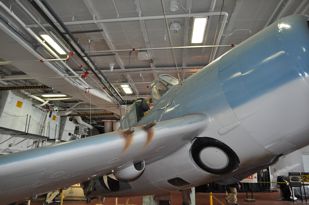
II. The underside photo shows
the exhaust arrangement for F4F-3 and
F4F-4 Wildcats. (CB)
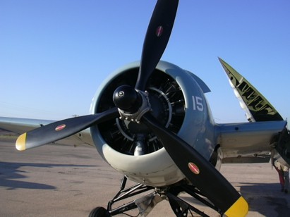
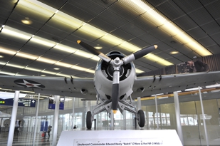
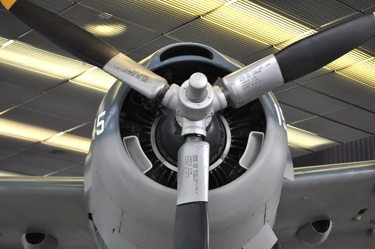
The propeller fitted
to the SDASM's and
O'Hare examples
(first two photos)
illustrate the
original cuffed
Curtiss Electric
propeller and hub as
fitted on the F4F-3,
F4F-4, FM-1 and Martlet
III. A few
FM-2s were also
produced with the
Curtiss Electric,
but utilized wide
chord blades.
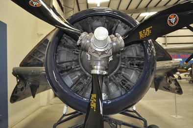
The third and fourth
photos show the
un-cuffed Hamilton
Standard propeller
as used on the Martlet
I, Martlet IVs
and some
FM-2s.
The final two show
the un-cuffed
Curtiss Electric as
fitted to the Martlet
IIs and some
FM-2s. (CB)
There
are three different intake arrangements on the F4F/FM
series of Wildcats. The first type was used
on early and final production F4F-3s as well as the
F4F-4. This type had three intakes; one on the top of
the cowl and two inside the lip of the cowl at
approximately the 4 and 8 o'clock position. The
upper one was for the carburetor intake, while the other
two were for intercooler air. (CB) The second type
moved the carburetor intake inside the top of the
lip. This was purportedly due to issues with the
effectiveness of the intake. In any case, the
intake on top was restored in the F4F-3 and used for the
entire F4F-4 and FM-1 production runs. (CB) The
third type was the version found on the FM-2, where
there were four intakes at approximately the 4,5 7 and 8
o'clock positions. The two lower ones were
to provide cool air to the oil cooler and the two upper
ones were carburetor intakes. (CB)
Gun Arrangements
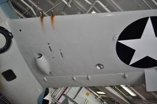
The pictures in the top row show the
four gun arrangement of the F4F-3, while
the first photo on the lower row shows
the six gun arrangement for the F4F-4
and Martlet II/IV. To the
right is for the four gun arrangement on
the FM-1, FM-2 and all four gun Wildcat/Martlet
aircraft with non folding wings,
with the exception of the Martlet I
having its own unique layout.
A few parts...
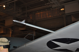
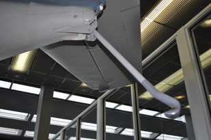
The pitot tube on the F4F-3 was a
straight tube mounted in the port wing.
When folding wings were introduced on
the Wildcat the pitot tube
would have struck the ground ,so the
curved example was introduced to protect
the head from damage. (CB)
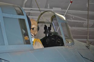
The windscreen
and canopy were pretty much unchanged
through out the production of the Wildcat,
though some Martlets had
additional framing in the
windscreen. The Mark 8 gun sight
was carried through much of the
Wildcat's service life. The FM-1
tail shows the shorter tail used on
all versions except the FM-2 (and
XF4F-8) and the shot on the right is
of the taller FM-2 tail.
(CB)
Left: The fairing
for the oil coolers on most Wildcat/Martlet
airplanes, one under each wing.
With the FM-2 the oil cooler was
behind the engine and cooling air was
ducted through the cowling. (CB)
Middle: The
hook under the keel, below and in
front of the wheel, is the attachment
point for the catapult bridle. When
launching from aboard ship the bridle
which had a loop at each end
would be attached on one end to the
catapult shuttle and the other end
would slide over this hook. When
the catapult shuttle reached the end
of its run the hook would slip from
the loop as the aircraft was slung
into the air. (CB)
Right: An
illustration of the arrestor hook in
the extended position. (CB)
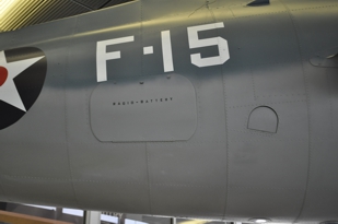
Far right: The door
covering the battery/baggage
compartment. Various items such
as tool would be stored there.
The jury struts to hold the wings in
the folded position on later Wildcats
were stored in this compartment. (CB)
|
|
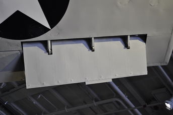
These shots give a
good idea of the appearance of the
fabric covered control surfaces and
can be used for comparisons to various
model kits. (CB)
Pratt
& Whitney R-1830 Twin Wasp
|
|
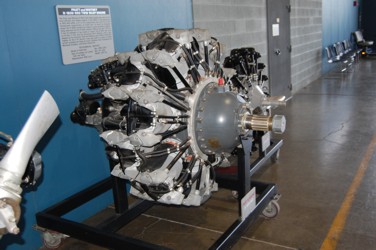
The R-1830 used
in the F4F was rated at 1,200 hp and
was the engine most associated with
the Wildcat. Used in the F4F-3,
-3A, -4, FM-1, Martlet II, III and the
Wildcat V the Twin Wasp was a very
reliable engine. It also powered
other well known aircraft like the
C-47 (and R4D) and the B-24 and is
considered to be the most produced
aircraft engine in history, with
173,618 produced. Pratt &
Whitney has always been known for
producing dependable engines and in
the days of recipes there was a
saying: "If you want to be able to fly
fast for a short time you want a
Wright, but if you want to be able to
fly for a long time use a
P&W!" This example, an
R-1830-92, is on display at the
Smithsonian's National Air and Space
Museum on the Mall in Washington,
D.C. While most likely a
civilian engine (probably from a
DC-3), it does provide reference of
the appearance for this great
engine. (CB)
An R-1830-90C on
display at the National Museum of the
United States Air Force. This
model is very similar to the ones most
commonly used to power the F4F-3,
F4F-4 and FM-1 Wildcat.
(CB)
Some specs:
SPECIFICATIONS
Model: R-1830-86
Type: 14-cylinder, air-cooled, twin row radial
Displacement: 1830 cu.in.
Max.
RPM: 2,400 (2,700 Military Power)
Max.
HP: 1,200
Weight: 1,467 lbs.
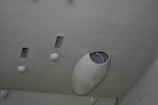
The P&W powered Wildcats
had two exhausts under the forward
fuselage. The third port between the two engine
exhaust was to dump waste air from the
intercoolers. On the F4F-3A which was only
equipped with a single stage supercharger
that exhaust was unnecessary.
Wright
R-1820 Cyclone
The Wright Cyclone was another
excellent engine, powering the FM-2, Martlet
I, IV (F4F-4B) and of course the Wildcat
VI. With this engine the
rate of climb for the FM-2 Wildcat
improved to approximately 3.200
fpm. This engine also provided
better takeoff performance making the
FM-2 better suited for use from the
small deck of CVEs. Some of the
final variants of the R-1820 could
produce over 1,500 hp. This
engine was also widely used powering
such aircraft as the B-17, R4D-8
(C-117D) and the S2F (S-2) Tracker.
The first photo shows an
R-1820-97 that powered the B-17 and is
on display at the 390th BW Memorial
Museum located at the Pima Air
Museum. The second and third
photos show an R-1820-103A on display
at the War Eagles Museum. (CB)
Some more specs:
SPECIFICATIONS
Model: R-1820-56 and -56W
Type: 9-cylinder, air-cooled, single row radial
Displacement: 1823 cu.in.
Max.
RPM: 2,600 (2,700 for -56A and -56WA)
Max.
HP: 1,350
Weight: 1,329 lbs
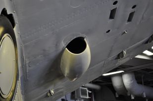
The FM-2 had an exhaust on
each side of the fuselage above the wing and two under
the forward fuselage. Those two are visible in
the second photo forward of the landing gear.
The catapult hook used on all versions of the Wildcat
is also apparent in that photograph.
(CB)
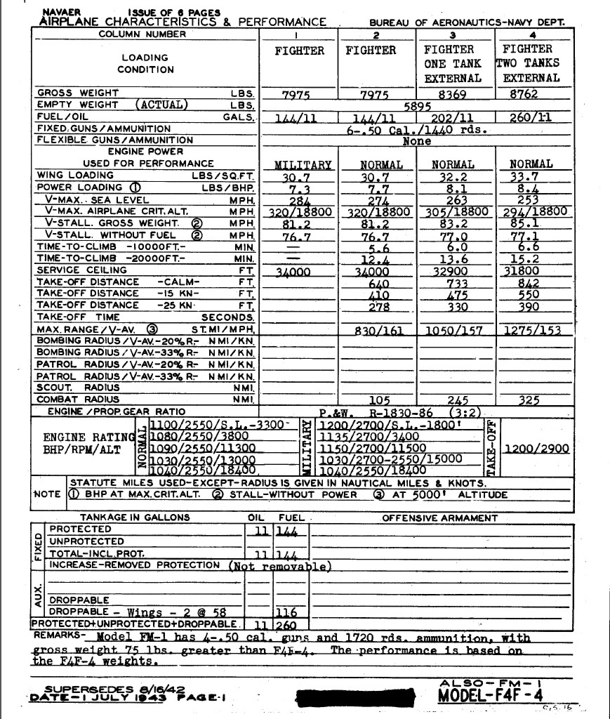
(While
the two charts above are not exactly "apples to
apples", they do provide some interesting data on
both the Twin Wasp and the Cyclone.)
To
navigate to:
Or to move on:
For your comments, suggestions, or
corrections:
Created
04-08-04
Modified
10-12-19
Clifford
Bossie