Here is a complete superhet radio you can build from parts you order from Antique Electronic Supply. The best part of this project is that it is complete. You don't need any external power supply or amplifier to make it work. Here is the schematic diagram.
For a verbal description click here.
The IF transformers are home made as shown elsewhere on this site.
The RF parts used are all from Antique electronic Supply. The variable capacitor is the triple 365 pf one. I am using one I already had on hand so I don't have the one from AES in hand. I don't know if it has trimmer capacitors on it. Mine didn't so I used external ones. They are 7 to 45 pf. If you run out of range at the high end try connecting a fixed capacitor in parallel with the trimmer. That isn't likely to happen except on the oscillator trimmer.
For the padder in the oscillator use one of the same trimmer capacitors used to make the IF transformers. I'm sure you will have to connect a fixed capacitor in parallel with the trimmer. Start with a 470 pf and go up or down as necessary. Run the oscillator coil slug almost out of the coil. You may even have to remove it to obtain best tracking.
To align the oscillator connect a frequency counter to the plate of the converter, 6BE6, tube. Remember there is B+ here and if your counter doesn't have a DC blocking capacitor at it's input you will need to connect one externally. I suggest tuning for a coverage of 535 to 1705 kcs. The oscillator is above the station frequency by the IF. For an IF of 455 kcs the oscillator range is 990 to 2160 kcs. If you use an IF of 315 kcs, as discussed below, the oscillator range is 850 to 2020 kcs.
Set the capacitor to the low end, fully meshed, and adjust the padder for the proper low frequency. Turn the tuning cap to the high end and adjust the trimmer for the proper high frequency. Repeat this procedure until the capacitors don't need to be changed anymore.
Now the noise from fluorescent lights comes in handy. At the low end of the band adjust the slugs in the antenna and RF coils for maximum noise. Adjust the RF and antenna trimmers for maximum noise at the high end. Repeat this until the adjustments no longer need to be changed. If you find the RF stage is oscillating decrease the value of the 47 k ohm resistor which is across the plate side of the RF transformer. If the receiver seems to go dead in the middle of the band change the slug in the oscillator coil, or remove it, and repeat all of the adjustments. You may have to find a compromise adjustment especially if you use an IF of 455 kcs.
Oscillator tracking is a problem with this radio. The reason is that all three sections of the variable capacitor are equal. It is impossible to get perfect tracking with this capacitor and a padder. If you can get your hands on a three section cap in which one section is smaller than the other two by all means use it, eliminate the padder, and put the slug back in the coil. The AM broadcast band is the most difficult of all radio bands to cover because it has such a wide ratio of upper to lower end. It's not the number of kilocycles or megacycles that are covered but the ratio that matters
These three section caps with one section smaller than the others are found in All American 6 radios and most portable tube radios. Portables usually had an RF stage to give the best sensitivity for use under difficult receiving conditions.
Because we have made our own IF transformers there is no special reason to use 455 kcs for the intermediate frequency. 455 was not divinely inspired and is in no way sacred. I tuned them down to 315 kcs and the tracking improved tremendously. I would have to open up the little boxes and add some fixed capacitance in parallel with the trimmers to get them down to 262.5. If you do this you will likely need to add more fixed capacitance in parallel with the oscillator padder. Putting the slug back in the oscillator coil will not have a positive effect on things. The bandwidth seems to be a little narrower than it was at 455.
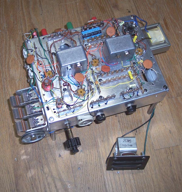
If this radio is to be built on a permanent chassis, and I might just do that myself, I would put the tubes, IF transformers, and the RF coil on top, and the antenna and oscillator coils underneath.
Layout is fairly critical. The .1 microfarad capacitors, the large orange round disks in the photo, should be as close as possible to the tube and IF or RF transformer they go with. The cathodes of the two 6BA6s and the 6BE6 are above RF ground. The heater circuit can be a source of signal transfer unless steps are taken to prevent it. The two caps shown on the heater lines should be some distance from the tubes and twisted wires run to each tube individually. I didn't put caps at the tubes although I might do that in a permanent version. I did have some trouble with oscillation of the RF amplifier. The .01 caps on the AGC should be close to the RF or IF transformer they go with.
Home.This page last updated July 4, 2005.