For a verbal description click here.
Now we are ready to recover the audio from the radio wave. The way we do that is exactly the same as a crystal set. A crystal detector could be used here but most tube radios use a vacuum diode because the tubes are already there. If you haven't looked at it go and checkout the page on How AM Works.The Detector Circuit.
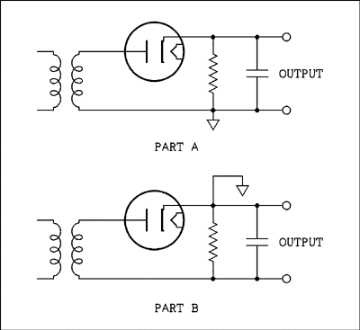
The circuit as it is connected in the radio may be a little puzzling. It's a matter of where the ground is connected. In most cases the placement of a ground symbol on the diagram has no effect on the actual circuit. Ground exists primarily in the human mind. Unless there are two grounds in conflicting locations and they are actually connected the circuit is not effected by the placement of grounds. Look at the diagram below.

For a verbal description click here.
Part A likely looks familiar. The signal from the IF transformer is coupled to the diode plate and the rectified pulses of current charge up the capacitor and the resistor discharges the capacitor between pulses. The discharge is slow enough that the output level remains fairly close to the peak level but fast enough to follow the audio frequencies as the waves rise and fall.Now in part B the ground has been moved to the cathode of the diode. Except for that the circuit is unchanged. It may look as if the audio is being taken off the end of the IF transformer instead of the diode cathode. In reality you always need two terminals to get a signal. In both diagrams the output signal is being taken off between one end of the IF transformer and the diode cathode. The only difference between the two is where the ground symbol has been drawn.
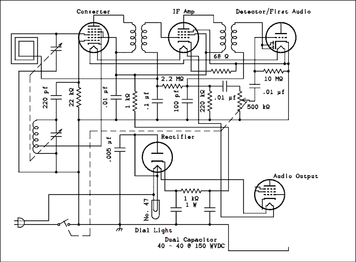
Now here is the radio circuit to date. The two diodes in parallel act as one and rectify the IF signal exactly like part B of the figure above.

For a verbal description of newly added parts click here.
For a verbal description of the complete diagram click here.
The bottom end of the IF transformer winding goes to the junction of a 2.2 megohm resistor, a 100 pico farad capacitor and a 220 k ohm resistor. The 100 pf capacitor charges up to near the peak value and holds almost all of it until the next cycle comes along. The capacitor can discharge fast enough to follow the changes due to audio. The audio signal appears across the 220 k ohm resistor and is coupled through the .01 microfarad capacitor to the 500 k ohm volume control. There is a DC voltage across the 220 k ohm resistor and the capacitor blocks it from getting to the volume control. If the DC were allowed to get there it would increase the likely hood of a scratchy sound when the control is turned. The signal from the volume control's slider or wiper is coupled through a .01 microfarad capacitor to the grid of the first audio amplifier but I seem to be getting ahead of myself again.I mentioned a DC across the 220 k ohm resistor. The voltage is proportional to the strength of the station which is tuned in. This voltage is negative. The 2.2 meg ohm resistor and .1 microfarad capacitor form a filter which removes the audio signal leaving only the DC. The stronger the station the more negative is the voltage appearing at the junction of the 2.2 meg ohm resistor and the .1 microfarad capacitor. This point connects to the low ends of the first IF transformer secondary and the loop antenna. Both of these coils have relatively low resistances and so the DC at the bottom ends is passed on to the tube grids to which each coil is connected.
Grid 3 of the converter tube and grid 1 of the IF amplifier tube are "remote cutoff grids". At a given voltage the tube will have a certain amount of gain. If the grid is made more negative, the gain is reduced. The more negative the grid the lower the gain. Do you remember that a stronger station produced a more negative voltage from the detector? The stronger the station the lower the gain. This is "automatic gain control" AGC. It is true that as you tune across the band you have to do some changing of the volume control as you tune in local stations as opposed to out of town or distant stations. Without this AGC the effect would be a lot worse and those local stations would drive the IF amplifier into saturation and the sound would be very distorted. In receivers that have an RF amplifier ahead of the converter and two IF amplifiers after it the AGC works so well that you often can't tell if a station is local or distant just by listening to it.
Now let's go back and look at that detector circuit again. The tube designers made a single tube with a triode and two diodes in one envelope. Some radio designers seem unsure what to do with that other diode. Many just connect the two in parallel as I have shown. Others try to figure out something else to use it for. One radio I recently took apart (its case was badly cracked and so it had no antique value, it is a source of spare parts) had the other diode plate connected to the junction of the 2.2 meg ohm resistor and the .1 microfarad capacitor. I don't know that it would serve any useful function there. I'm going to do some experimenting to see what effect it would have.
Or use your "Back" button to return to where you were.
Thank you for visiting my page at Angelfire.
Please come back and visit again!This site begun March 14, 2001
This page last updated August 1, 2002