
Many of you may know that a cyclotron is a sub atomic particle accelerator. So what the heck is a circlotron. Well, it's a power amplifier configuration that was developed in the 1950s. It is called a circlotron because the original idea diagram was drawn as a circle. The best I can do with my graphics program is to show it as a bridge. It's promise is very low distortion. It's cost is a total of 3 power supplies, none of them connected in common.Some amplifiers were commercially produced using this circuit. They were high end units because of the high cost to produce. The circuit never caught on because the design had shortcomings which caused it to be unreliable. Here is the simplified schematic of a circlotron power output stage.
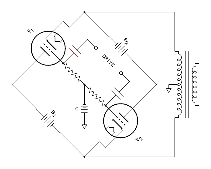
Figure 1 Circlotron Amplifier Drawn as a Bridge.
For a verbal description click here.
The disadvantages are,B1 and B2 aren't really batteries but represent totally floating power supplies. The battery marked C is the bias supply. Because each power supply has its negative terminal connected to one side of the output transformer, each channel of a stereo amplifier requires its own pair of power supplies. Commercial stereo amplifiers would have been made with a power transformer having 5 B+ windings. Two for each channel and the fifth for the preamp, drivers, and bias supply.
- The number of power supplies required.
- The extremely large drive voltage needed.
Note: The bias supply is usually stolen from the B+ winding, or a tap on it, so a separate bias winding was not necessary. The positive of the bias battery is grounded so a single supply could have been used for both channels.Each tube is working as a cathode follower so its gain is a little less than unity. For a 50 watt amplifier the driving voltage is more than your airconditioner needs to run. It is not easy to develop this much audio voltage, even at low power, without introducing a lot of distortion.Some readers have objected to the use of the term "cathode follower" to characterize the tube configuration in this circuit. They argue that the plate is supplied a signal which is out of phase with the grid and cathode voltage which is not the nature of a cathode follower. However, This is a byproduct of the circular configuration and if it were possible would not be a part of the design. In spite of the plate voltage variation each tube still behaves as a cathode follower, having a gain of slightly less than unity and the cathode following the grid voltage.The advantages are,The special configuration makes the circuit act as a bridge amplifier but with only two active devices rather than the usual four.
Theoretically, the optimum load impedance is 1/4 of the recommended impedance for the same tubes in a conventional push-pull connection. The output transformer will need less inductance so the primary will have fewer turns. This makes it easier to get the low end down to 20 cycles. Fewer turns means less stray capacitance and that will give the transformer a better high end. The self resonate frequency will be higher which makes it easier to compensate the global feedback loop if one is used.
- Low impedance primary on the output transformer.
- No DC in the output transformer.
- Low distortion with little or no global feedback.
Also, the drive is applied to the whole primary winding all the time. Unlike a conventional push-pull amplifier. In a class AB push-pull amplifier when one tube goes into cutoff, the instantaneous current is flowing from the center-tap to the plate of the conducting tube through only half of the primary. If you look at the diagram above you can see that when V2 is in cutoff, electrons flow from the top of the transformer to the cathode of V1, through V1 to the positive of B1, out of its negative, to the bottom of the transformer, and up through it to complete the circuit. When V1 is in cutoff, the electron current path is from the bottom of the transformer, through V2, B2 and down through the transformer. This uses the entire primary winding. While the center tap is grounded the only other ground is to the grids which are high impedance points and are not involved in the current flow. This is why the transformer can have 1/4 of the impedance of that for a conventional push-pull circuit.
No DC in the output transformer primary means that core saturation is never a problem, unless the tubes are poorly matched. Without any DC to conduct the primary can be wound with finer wire and since it has fewer turns to begin with, it can be smaller and les costly.
A cathode follower is an amplifier with essentially 100% feedback. It should be, and usually is, a low distortion amplifier. If the driver is well designed, global feedback may not be needed at all.
Pentodes, the Screen Voltage and All That.
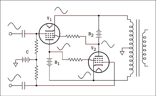
Figure 2 Circlotron Output Using Pentodes.
For a verbal description click here.
If the screen grid were to be connected to the plate, the pentode would be triode connected. The circuit has to be arranged so the voltage between the screen grid and cathode stays constant as the plate voltage, potential difference between the plate and cathode, changes. The circuit in Figure 2 shows how this is accomplished.The resistors in the screen grids are not large, ranging from 100 ohms to 1 k ohm depending on tube type. The wave forms show that by connecting the screen grid of one tube to the plate of the opposite one provides the screen with a signal which is in phase with the cathode voltage but above it by the value of the B batteries. Notice that B2 is connected between the cathode and screen of V1 and B1 is connected between the cathode and screen of V2. This allows the tubes to have the higher transconductance of the pentode connection rather than the lower Gm of the triode connection. A higher transconductance means a lower output impedance, gain closer to unity, and less overall distortion.
Proper Load Impedance.
The impedance at the cathodes of the tubes is very low so the amplifier is basically a voltage source. That gives it something in common with the modern transistor amplifier. It doesn't make any difference what value of load impedance is connected as long as the amplifier can deliver the current demanded by the load at the given power level.Let's work out some numbers for power levels of 25 and 50 watts. First of all, in the following tests I'll be using two 500 volt power supplies for B1 and B2. If the transfer function of the tubes went in a straight line right down to zero, the peak voltage across the load (output transformer primary) would be 500 volts. Unfortunately, tubes don't have that kind of transfer function.
A very conservative minimum voltage for most power pentodes is 100 volts. Therefore, the maximum, peak, voltage across the load is 400 volts.
VRMS = 400 divided by the square root of 2.
VRMS = 400 / 1.414 = 283 Volts.
Now if we want 50 watts from this amplifier we need an impedance of,
R = V squared divided by P
R = 2832 / 50 = 1.6 k ohms.
For 25 watts we need a load impedance of 3.2 k ohms.
Load Impedance.
I set up the circuit with a Hammond 1650K, 50 watt, ultra linear, 3.4 k ohm plate-to-plate, output transformer. For use in a Circlotron, this transformer can be wired in one of three ways.Wired normally it will present a theoretical load impedance of 3.4 k ohms. The measured impedance is 3.6 k ohms. That's a little above the 3.2 k ohms needed for a 25 watt amplifier so we should expect less than 25 watts in this configuration.
The other way to operate it is at half impedance. That is wire the secondary for 16 ohms and terminate it with an 8 ohm load. According to theory this should give an impedance of 1750 ohms but the measured value is 1840 ohms. This is not recommended by the manufacturer but I can hope they don't send the impedance police after me. Once again this is high for a 50 watt amplifier so we won't get 50 watts when wired this way.
Another way to wire the transformer and defy the impedance cops is to use the screen taps instead of the plate taps and wire the secondary for 4 ohms. When the secondary is connected to an 8 ohm load the measured impedance between the screen taps is 1,160 ohms. Based solely on voltage this would give us 69 watts but the maximum current the tubes can deliver will begin to limit the power long before that level is reached.
In the tables below the values of impedance presented by the transformer will be stated in the column headings.
At least that's the theory.
I have never heard one of these amplifiers in operation. In fact I had never heard of the circuit until the subject came up on the Fun With Tubes email list. So after I show the circuit with a high output driver, we will see how a circlotron works in the real world.A real amplifier.
This is where the rubber meets the road. The push-pull driver in my carefully designed Amplifier Test Bed will deliver 400 volts peak-to-peak from each side at about 0.7% distortion. That works out to 283 volts RMS grid-to-grid. The calculations above indicate we need a voltage of 283 volts cathode-to-cathode. The grid-to-grid is going to be more than that because the gain of the cathode follower like stages will be somewhere between 0.8 and 0.9. I spent many hours in the laboratory using the test bed but it just doesn't seem worth reporting on. At first glance it seems to deliver enough voltage but this is still not the solution. The test bed driver doesn't provide quite enough output and at the very high levels has too much distortion. It is also too complicated and power hungry to be used in a practical amplifier. Therefore, the results from tests involving it would seem to be only of academic interest.We will skip all that and go directly to a bootstrapped driver using a 12AX7 that will deliver plenty of voltage for the purpose.
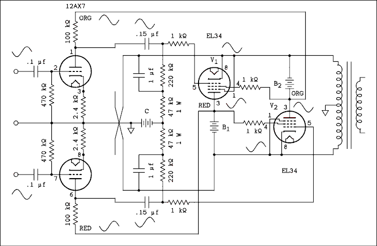
Figure 3 Driver and output stages using EL34s.
For a verbal description click here.
B1 and B2 are Hewlett Packard 712B power supplies, 0 to 500 volt at 200 mA, regulated. For the test each one was set to 500 volts and the bias adjusted for a no signal current meter reading of 30 mA per power supply. The bias was derived from the bias supply in the test bed. The dead end lines are so local feedback resistors can easily be dropped into the diagram.As shown in the above diagram the plate load resistors of the driver triodes are connected to the positive end of B1 and B2. This provides a quiescent plate supply voltage of 500 volts but when signal is applied the plate supply voltage goes up at the same time that the plate voltage goes up and visa versa. The waves drawn in the circuit indicate this. This is what is known as bootstrapping. It makes the plate resistor appear much larger than it actually is. This increases the gain and decreases the distortion. Also, it tremendously increases the output voltage capability of the stage.
Note that there is a 1 microfarad capacitor connected from the cathodes back to a tap on the grid resistors of each EL34. This is known as bootstrapping the grid resistors and has the same effect of increasing the effective resistance. This also works to decrease the amount of distortion in the triode stages. The effective load resistance of each triode is approximately 4 meg ohms. This page originally presented before and after data on the addition of bootstrapping of the grid resistors but I think it is sufficient to say that the distortion was decreased and the output voltage before clipping was increased.
Distortion Versus Power.
Data for all three connections of the output transformer are shown.
Power,
(Watts).Distortion,
Percent.
3,600 ohm load.Distortion,
Percent.
1,840 ohm load.Distortion,
Percent.
1,160 ohm load.50 -- -- 2.9 32 -- 2.20 1.8 20 2.5 -- -- 16 2.3 1.45 1.8 8 1.3 1.40 1.7 4 0.83 1.20 1.6 2 0.59 0.96 1.45 1 0.41 0.74 1.25
Distortion Versus Frequency at half power.
Frequency,
(cps).Distortion,
Percent.
3,600 ohm load.Distortion,
Percent.
1,840 ohm load.Distortion,
Percent.
1,160 ohm load.20 3.15 1.20 25 * 30 1.55 1.20 24 40 1.35 1.20 4.7 50 1.2 1.20 2.15 100 1.3 1.30 1.8 300 1.5 1.30 1.75 1,000 1.6 1.50 1.85 3,000 1.8 2.35 2.0 10,000 2.3 6.1 3.8 15,000 2.35 7.1 4.6 20,000 2.1 8.1 4.7 * Power = 8 Watts.
This looks pretty good. The addition of global feedback to the circuit as it stands would probably bring the distortion down to a quite respectable level but the circlotron is supposed to start out at about 0.25% and may not need any global feedback if some local is applied around the output.
Local Feedback.
The next step is to put in the feedback resistors that I left room for in the schematic.
Figure 4 Circlotron Amplifier with Some Local Feedback.
For a verbal description click here.
Distortion Versus Power.
Power,
(Watts).Distortion,
Percent.
3,600 ohm load.Distortion,
Percent.
1,840 ohm load.Distortion,
Percent.
1,160 ohm load.50 -- -- 0.78 32 -- 0.60 0.40 20 0.56 -- -- 16 0.49 0.40 0.44 8 0.31 0.34 0.43 4 0.095 0.265 0.42 2 0.055 0.20 0.39 1 0.070 0.14 0.34 Distortion Versus Frequency at 1/2 power.
* Power = 8 watts.
Frequency,
(cps).Distortion,
Percent.
3,600 ohm load.Distortion,
Percent.
1,840 ohm load.Distortion,
Percent.
1,160 ohm load.20 0.39 0.24 3.9 * 30 0.29 0.17 2.9 40 0.27 0.16 0.90 50 0.25 0.18 0.40 100 0.27 0.21 0.36 300 0.28 0.23 0.35 1,000 0.265 0.41 0.39 3,000 0.26 1.0 0.48 10,000 0.55 2.85 1.25 15,000 0.87 3.4 1.65 20,000 1.1 5.7 2.0 Complete Circlotron Amplifier.
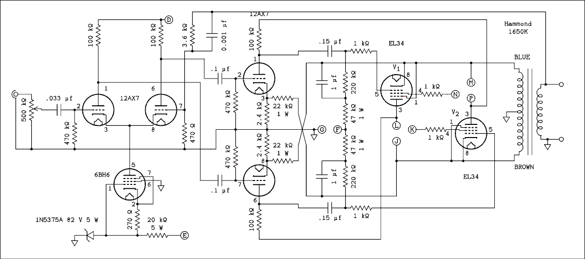
Figure 5 Complete Circlotron Amplifier.
For a verbal description click here.
The letters inside the circles refer to connections on the power supply schematic below. D connects to D, F to F, etc. I avoided using the letters A, B, and C, because these letters have special meanings in electronics.The amount of global feedback is very close to 10 dB except when the load of 1,160 ohms is used. In that case the feedback is 14 dB. Increasing it to 20 dB would have likely improved the distortion figures even more but I was not inclined to work out the frequency compensation to make it stable with that amount of feedback.
Distortion Versus Power.
Power,
(Watts).Distortion,
Percent.
3,600 ohm load.Distortion,
Percent.
1,840 ohm load.Distortion,
Percent.
1,160 ohm load.50 -- -- 0.215 32 -- 0.165 0.12 20 0.27 -- -- 16 0.25 0.12 0.125 8 0.24 0.11 0.125 4 0.060 0.080 0.120 2 0.035 0.060 0.110 1 0.030 0.052 0.095 Distortion Versus Frequency at 1/2 power.
* Power = 8 watts.
Frequency,
(cps).Distortion,
Percent.
3,600 ohm load.Distortion,
Percent.
1,840 ohm load.Distortion,
Percent.
1,160 ohm load.20 0.22 0.13 0.93 * 30 0.11 0.12 0.65 40 0.11 0.11 0.41 50 0.125 0.12 0.17 100 0.265 0.11 0.15 300 0.125 0.105 0.12 1,000 0.27 0.095 0.12 3,000 0.215 0.26 0.125 10,000 0.24 0.80 0.19 15,000 0.30 1.15 0.25 20,000 0.39 2.6 0.60 Power Supply.
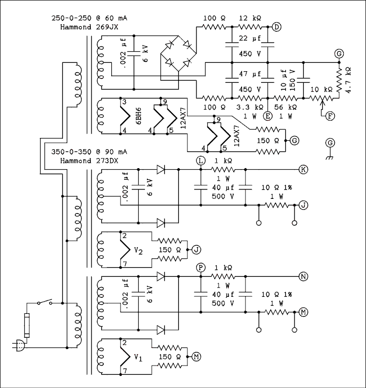
Figure 6 Power Supply for 25 Watt Circlotron Amplifier.
For a verbal description click here.
You may be tempted to build the power supply on a separate chassis but it is not recommended. The reason is capacitance. With B1 and B2 floating and having the audio signal on them, the capacitance to ground can and does, effect the high frequency performance of the amplifier. If you place the power supply chassis behind your audio equipment rack the extra capacitance of the connecting cable could be enough to disrupt the performance. Also the cable is going to radiate the audio signal and could lead to feedback if some signal source is placed too close to it. For these reasons the power supply should be on the same chassis with the amplifier. A monoblock for each channel would probably be the best approach.Adjustments.
- Before turning on the power, turn the bias pot to the extreme that will give the most negative voltage. This will place the wiper closest to the 10 microfarad 150 volt capacitor.
Connect a DC voltmeter across one of the 10 ohm 1% resistors and set it so you can accurately read a voltage of 300 millivolts.
Connect the amplifier output to an 8 ohm 25 watt resistor. If you don't have one connect it to an 8 ohm speaker.
Turn on the power and allow at least 1 minute to ensure that all tubes are properly warmed up.
You should not hear any sound in the speaker and most likely won't see any reading on the voltmeter.
Slowly turn the bias pot until you see a voltage. Adjust the pot for 300 millivolts. If you invested in a matched pair of tubes the voltage across the other 10 ohm resistor will be very close to 300 millivolts.
If you are using an 8 ohm resistor and you have an oscilloscope and audio generator, feed the generator to the input and observe the wave on the output. It should go slightly higher than 47 volts peak-to-peak without showing any clipping.
If you have only a speaker and FM tuner or CD player connect them to the appropriate in and out points on the amplifier and enjoy.
Conclusions.
The main advantage of the Circlotron configuration appears to be that it will extend the low end of Hammond transformers to 20 cycles. The exception to this is when the screen taps are used to obtain more power. Combine that with their higher efficiency and they become the transformers of choice over the Edcors.The circlotron works like a bridge amplifier but with only 2 active devices instead of the usual 4. The price that must be paid for this is the need for two completely floating power supplies for each channel.
The distortion is quite low as long as the load impedance is high but if it is lowered to the point where 50 watts of power is produced the distortion becomes quite high and does not seem to be reduced at low power levels as we are accustomed to finding in other amplifier configurations.
The distortion does not appear to be any better than a well designed ultralinear amplifier. Based on this I'm not ready to junk out my EL34 ultra linear and build a circlotron.
A poor man dreams of wealth,
A wealthy man dreams of wisdom,
And a wise man dreams of tubes aglow, all in a row.
Amplifier Smorgasbord.Or use your "Back" button to return to where you were.
This page last updated May 22, 2007.