For a verbal description click here.
Now we have reached the part that can make or break an amplifier design. A poorly designed output can make an otherwise good amplifier sound terrible. A unit which has been properly designed from phono input to power output will give that wonderful tube sound that makes listeners mouths drop open in amazement.Why Push-Pull?
Why not. You can get more power out of two tubes than one. You may be surprised to learn that you can get more than twice the power out of two tubes in push-pull then you can get out of just one. In simple terms it's like two people cranking a human powered winch. There are two cranks, one on each side of the winch. The two cranks are 180 degrees apart and just when one man gets to that part of the circle where he is lifting and pushing away on the crank (his weakest point) the other man is pulling down and toward himself (his strongest point). It works much the same way with two tubes in push-pull. They are working 180 degrees apart and when one tube is in a condition where it is making the weakest contribution to the power the other tube is at its strongest.The other good reason is distortion. When distortion occurs harmonics (integer multiples of the frequency) are created that weren't there before. This gives music a highly unnatural sound. The new frequency which is twice the original frequency is called the second harmonic, the one which is 3 times, the third and so on. What happened to the first harmonic? That's the original frequency. Tubes in push-pull cancel even numbered harmonics which were not part of the original input signal. The strongest distortion product is almost always the second harmonic so if you cancel it out you have greatly reduced the amount of distortion. Don't worry, I'm not going into the mathematical proof of this cancellation.
Classes of Amplifiers.
You knew it had to happen sooner or later. I have to tell you what the difference is between class A, AB1, AB2, B and C amplifiers. So hang on tight because here we go.Class A Amplifier.
The resistance coupled amplifiers we have already studied are class A. In such an amplifier plate current flows over the entire input wave cycle. A resistance coupled amplifier won't work right in any other class. Single ended power amplifiers, such as those used in All American 5 radios are always class A. The theoretical maximum efficiency is 50% but in practice, consider yourself lucky if you can get 20. Theoretically the average, DC, plate current will NOT change from zero signal to maximum power output. In a push-pull output stage practice often comes very close to theory.A single ended class A amplifier is a different story. Such an amplifier can meet the conditions of class A but still show a considerable increase in plate current from zero signal to maximum signal. This is because the tube is not a perfectly linear device. When the plate current is high it will increase by a larger amount for a given change in grid voltage as compared to when the plate current is small.
In a push-pull amplifier this effect is almost un noticeable because the nonlinearities of the two tubes cancel each other and produce a nearly linear transfer function. Many audiophiles favor class A outputs because of the lower distortion which results. However a well designed AB1 output can sound just as good as a class A and run a lot cooler.
Remember the definition. Class A, the plate current of both tubes is flowing uninterrupted over the entire cycle.
Class B Amplifier.
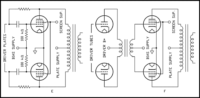
Hold it, what happened to AB1 and AB2? As you may already know or have guessed class AB is a hybrid of pure class A and B. After we learn what class B is then we will go back to see what those AB classes are all about.In ideal class B the plate current is zero when there is no input signal. When the signal appears each tube conducts over half of the cycle. The two tubes work alternately so the whole cycle is amplified. This assumes that the plate current versus grid voltage is a perfect straight line going right down to zero. Unfortunately, it is not. In order to avoid large amounts of distortion as the task of amplifying is being handed off from one tube to the other we have to allow some plate current to flow in the absence of input signal. The average, DC, plate current for maximum power output can be from 5 to 10 times the zero signal current. The class B amplifier that was the modulator for my AM kilowatt used a pair of 810 tubes which are power triodes. The idling current (plate current in the absence of audio signal) was about 60 milliamps and the peak current for 100% modulation was about 360 milliamps. (The plate voltage was 2000 volts.) The theoretical maximum efficiency for a class B amplifier is 78.5 % but in the real world expect about 60. In class B amplifiers the grid must always be driven positive for part of the cycle. That means that the grid draws current over that part of the cycle and a transformer must be used between the driver tubes and the power output tubes instead of resistance-capacitance coupling. A power amplifier with a transformer coupled driver is shown in Figure F below.
Just as a side note, a very popular transmitter used by small, 250 watt, AM broadcast stations and made by Collins Radio company was a pair of 810s for the RF power amplifier and another pair for the modulator. Stations running this rig were easy to spot, they had a terrific sound.Remember the definition. Class B, the plate current of each tube flows for approximately 1/2 of the cycle and the two tubes work alternately.Class AB1 Amplifier.
Class AB is intermediate between A and B. The 1 in AB1 means that grid current does not flow, the tube grids are not driven positive. A class AB1 amplifier will produce much less distortion than a class B amplifier using the same tubes. The distortion figures are often comparable to class A. The rise in plate current from zero signal to maximum power may be as little as 10 % to as high as 70 %.Remember the definition. Class AB1, somewhere between A and B but the grids are NEVER driven positive.
Class AB2 amplifier.
Class AB2 is closer to B than to A. The 2 means that the grids ARE driven positive and grid current will flow. An output stage in which there is grid current such as AB2 or B must be transformer coupled, as shown in Figure F, instead of R-C coupled. If R-C coupling IS used the grid behaves like the plate of a diode and rectifies some of the audio signal which makes the grids more negative. Instead of class AB2 you would have a kind of moving class AB1 and a lot more distortion than you had counted on. If you were to attempt class B with R-C coupling, the extra grid bias could actually bias the tubes beyond cutoff and lead to heavy distortion. The rise in average, DC, plate current may be anywhere from 50 % to 200 %.Remember the definition. Class AB2, somewhere between A and B but the grids ARE driven positive and there will be grid current.
Class A2 amplifier.
Some amplifier designs use a type of operation known as class A2. The tubes are running in class A but control grid current flows over some part of the input cycle. Tubes such as the 811A, a zero bias power triode, have to be operated in this mode because of their nature. Some other tubes may be operated this way depending on the tube and the load impedance.Class C amplifier.
Class C amplifiers are never used in audio. This section is given in the name of completeness. They are used as radio frequency power amplifiers because of their high efficiency, approximately 80 %. They conduct plate current over 125 degrees, or less, of the input cycle. A resonate L-C circuit restores the wave to the familiar sine wave. The efficiency is so high because the tube conducts current only when the instantaneous plate voltage is low and is cut off when the plate voltage is high. That means the tube dissipates little power and most of it goes to the antenna.Cathode Bias or Fixed Bias.
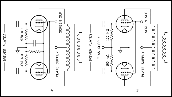
In cathode bias the cathode current of both tubes is allowed to flow through a resistor to ground which develops a positive voltage on the two cathodes. As the grids are held to ground potential by the resistors they are actually negative with respect to the cathode. For a more detailed discussion of cathode bias see Resistance Coupled Amplifier, a basic building block. Cathode bias is used with class A amplifiers ONLY. A cathode biased amplifier is shown in Figure A below. Engineers disagree about using a capacitor to bypass the cathode resistor. Some feel that leaving it off improves balance of the circuit and reduces distortion. Others will say that the amplifier will deliver more power at less distortion when being pushed to the limit. You pays your money and you takes your choice.
For a verbal description click here.
In Figure A the outputs from the driver, phase inverter or phase splitter are capacitively coupled to the grids of the two output tubes. As the signal on the grid of one tube goes positive the signal on the grid of the other tube goes negative. The plate current of the first tube increases while the plate current of the other tube decreases. B+ is applied to the center tap of the transformer primary so the steady state plate currents are flowing in opposite directions in the primary. As long as the currents are equal there is no net magnetic field from the primary coil. When the currents begin to change a changing magnetic field is produced. Because the currents are flowing in opposite directions an increasing current on one side has the same effect as a decreasing current on the other side. The changing magnetic field induces a voltage in the secondary winding which is connected to the voice coil of a speaker.In relatively low power tubes such as 6V6s or 6L6s the screen voltage can be the same as the plate supply voltage and the points labeled "plate supply" and "screen supply" may be connected together. In many amplifiers the screen grid voltage passes through an additional filter section so the two are not quite the same. In higher power tubes such as 6550s or 6146s the plate may run at 600 volts while the screens may be at 200 or 300 volts. For results to please someone with golden ears the voltage to the screen grids of any tube type should be regulated in some way.
In a fixed bias circuit, shown in Figure B, the cathodes are grounded and the power supply has been designed to develop a negative voltage which is applied to the grids through the resistors which formerly went to ground. Because the amount of bias voltage is not effected by the plate current, as it is with cathode bias, fixed bias should be used when the tubes are to be run in class AB1. Except for that the circuit operates the same as described above.
Triode Connected Amplifier
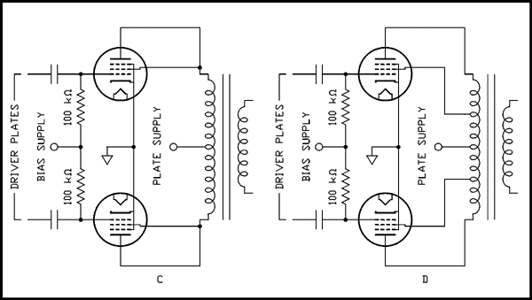
Because many people feel that pentodes produce higher levels of distortion than triodes, the triode connection is sometimes used. The people who designed and sold tubes made a ton of beam power pentodes but almost no power triodes. There doesn't seem to be much between the 6AS7G/6080WA (10 watts) and the 810 (600 watts. There is the 811A but that's a zero bias triode so even a class A amplifier using this tube would have to draw grid current.) To make a pentode act like a triode you connect the screen grid to the plate as in Figure C..
For a verbal description click here.
The major drawback seems to be that the maximum screen voltage now becomes the maximum plate voltage. Depending on what tube type you have that may cause a considerable reduction of power. Another disadvantage is that the triode connected tubes will require more driving voltage. If the driver is not well designed the improved distortion from the triode connection may be canceled out by an increase in distortion from the driver stage.The Ultra Linear Connection
Figure D is a compromise between triode and pentode connection. It's called the "ultra linear connection". Like any compromise it has all of the advantages of both along with all of the disadvantages of both. Its major disadvantage is that it requires a special output transformer. Not only that but the transformer has to be designed for optimum performance with a particular tube type.The paragraph which used to occupy this space put a knock on the ultra linear configuration. The reason was that I was performing the tests with tubes of the 6L6 family. This tube does not perform very well in ultralinear connection. The EL34 family was designed for this configuration. I have designed and built such an amplifier which is described elsewhere on this site. I listen to it every day.
The Cathode Loaded Output Circuit.
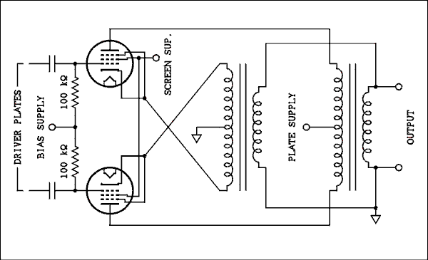
The cathode loaded circuit was described in an article titled "Amplifiers and Superlatives by D. T. N. Williamson and P. J. Walker Wireless World, Sept. 1952, pp. 357-361. At this time in history there seems to have been some transatlantic sniping over ultra linear versus cathode loading. I used to side with the British on this one. Williamson and Walker found that the so called ultra linear connection produced more distortion and delivered less power than a similar conventional pentode connection. Evidently they were using 6L6 tubes for their tests. The cathode loaded circuit they described looks like this.
For a verbal description click here.
The circuit above uses two identical output transformers. That could get expensive but the alternative is to get a custom made transformer which is likely to be even more expensive. So you pays your money and you takes your choice. If you want to take the time and have the design skill I would recommend the custom made route. A custom made transformer would have another center tapped winding similar in appearance to the plate winding.Some mistakenly believe that the only purpose for cathode loading is to apply negative feedback to the cathodes of the output tubes. I myself once was a member of that misinformed group. It is called cathode loading because part of the load is placed in the cathode circuit of the tubes. In an amplifier where the impedance of the cathode winding is equal to the impedance of the plate winding half of the power to the load comes from the plates and the other half from the cathodes. Such an amplifier was sold in the 60s.
There is an element of negative feedback just as there is in a cathode follower. This is no doubt responsible for the reduction in distortion claimed for these amplifiers. I have to say "claimed" because I have not tested this configuration for myself.
You might think that the feedback effect on distortion could be obtained by using separate cathode resistors and leaving them unbypassed. Transformer coupling the signal back to the cathodes is NOT the same thing. Unbypassed cathode resistors give current feedback as the fed back voltage is proportional to the cathode current, which is almost the same as the plate current, of the tube. With transformer coupled feedback the fed back voltage is proportional to the output voltage of the transformer. Current feedback increases the output impedance while voltage feedback reduces it. And as pointed out above feedback is only a part of the reason for using cathode loading. Power is being delivered from the cathodes to the load. In the case of equal impedance windings, half of it.
I have never heard a push-pull cathode loaded amplifier but I have a 1956 Silvertone tape recorder, still working, that uses a single ended cathode loaded 6V6 output circuit. It sounds better than the average single ended 6V6 amplifier.
Local feedback.
As I will discuss in detail in the next section I believe that it is possible to have too much overall feedback around an amplifier. Local feedback (around just one stage) should be used as much as possible. In fact the ultra linear and cathode loaded circuits discussed above are a form of local feedback. Figure E below shows another form of local feedback around the output stage. The resistors go from the plates of the output tubes to the plates of the driver tubes. This eliminates the use of an additional DC blocking capacitor. The two sets of plates are not at exactly the same DC voltage but they are close enough.
For a verbal description click here.
Transformer coupling.
If you want to run a large amount of power you will need to operate the output tubes in class AB2 or B. These classes of operation require the use of an input transformer as shown in Figure F. Audiophile equipment would never be designed this way. Even the output transformer is almost too much for golden eared listeners. Another transformer is over the line. You would find this only in ultra high power PA amplifiers and modulators for AM transmitters.Stop the presses, this just in.
People who view this site are constantly thinking. I received an email message suggesting that direct coupled cathode followers could be used as drivers and bias supply for a class AB2 or B output stage. I built and tested it. To view the circuit click here then use your back button to return. You will recognize the phase splitter. It's output goes to a push pull stage which I found in a 1950 tube manual for driving 6AS7G triodes. They need a lot of drive voltage and that's what this circuit gives. The original circuit used a 6SN7. I used a 6CG7 which is a 9 pin mini version of the 6SN7. When you look up a 6CG7 in a tube manual you are referred to the data for a 6SN7. The signal is capacitively coupled to another 6CG7 where each section is a cathode follower which is directly coupled to each grid of a pair of 6146s. A pot in the grids of the cathode followers sets the bias and therefore the idling current of the 6146s. This circuit is to be the modulator of a 200 watt AM ham transmitter I am building.Understanding Tube Manual Information.
Tube manuals give you lots of information on how to operate power tubes. The problem is that there is so much extraneous data and someone who is not an electrical engineer may have difficulty sorting out what is important and what is not.The best way to explain what is what is by example. The problem is that I can't just scan a page from a tube manual, post it and then tell you what it means. Copyright law you know. What I will do is to give data on a fictitious tube. Let's call it an XII124. I'm not going to give everything you are likely to find, jus what is important. Unless you are the type of person who likes to solve puzzles I don't recommend you spend a lot of time looking over the fake tube manual data below. Give it a quick look and then scroll on down to the explanation below.
Tube Type XII127
Beam Power Amplifier
Heater Characteristics
Heater Voltage ........................................................................ 12.6 volts. Heater Current ........................................................................ 1.25 Amperes. Maximum Heater-Cathode Voltage Heater Negative with Respect to Cathode ..................... 200 volts. Heater Positive with Respect to Cathode ...................... 100 volts.
Maximum Ratings
Triode Pentode Connection Connection -------------- -------------- Plate Voltage ...................................................................... 350 750 volts. Grid No. 2 Voltage ............................................................. -- 350 volts. Plate Dissipation ................................................................. 75 75 watts. Grid No. 2 Dissipation ........................................................ -- 8 watts. Grid No. 1 Resistance Fixed Bias .................................................................. 100 k 100 k ohms. Cathode Bias .............................................................. 470 k 470 k ohms.
Characteristics and Typical Operation.
Class A Amplifier Triode Pentode (Single Tube) Connection Connection ----------- --------- ----------- --------- Plate Voltage ...................... .................. 350 400 600 750 volts. Grid No. 2 Voltage ............................... -- 350 250 350 volts. Grid No. 1 Voltage ............................... -30 -20 -16 -25 volts Peak A F Signal Voltage ....................... 30 20 16 25 volts Plate Current (Zero Signal) .................... 105 125 100 95 mA Plate Current (Max. Signal) ................... 115 135 110 105 mA Grid No. 2 Current (Zero Signal) ........... -- 5.0 2.5 2.5 mA Grid No. 2 Current (Max. Signal) .......... -- 7.3 4.7 7.0 mA Transconductance ................................ 4700 6000 5300 5200 umhos. Plate Resistance .................................... 1700 22500 35000 33000 ohms. Load Resistance ................................... 2000 2500 4500 6000 ohms. Power Output ...................................... 5.0 11 20 32 watts Total Harmonic Distortion ..................... 5 10 12 16 %
Push-Pull Amplifier (Two Tubes) Class A1 Class AB1 Class AB2
-------- -------- -------- -------- -------- -------- Plate Voltage .............................. 250 400 400 600 600 750 volts. Grid No. 2 voltage ...................... 250 350 350 350 300 350 volts. Grid No. 1 Voltage ..................... -15 -20 -25 -30 -30 -30 volts. Peak A F Grid to Grid Voltage ... 30 40 50 60 75 100 volts. Plate Current (Zero Signal) ......... 200 150 100 50 50 55 mA Plate Current (Max. Signal) ........ 220 165 250 125 250 350 mA Grid No. 2 Current (Zero Signal) 30 12 8 5 5 5 mA Grid No. 2 Current (Max. Signal) 40 18 12 9 12 17 mA Transconductance (Each Tube) .. 5500 5700 5000 5300 4500 4000 umhos. Plate Resistance (Each Tube) ..... 24500 23500 26000 25500 28000 29000 ohms. Load Resistance (Plat to Plate) ... 3600 7200 4800 16000 8000 7400 ohms. Power Output ............................ 21 24.5 50 75 100 175 watts. Total Harmonic Distortion ..... .... 2 2 2 2 2 2 %
What It All Means.
The name "Beam Power Amplifier" refers to the geometry inside the tube. Instead of an actual grid used as the suppresser it is a gate that forms the electrons into a beam as they head for the plate. This concentration of electrons forms a negatively charged region between the screen grid and the plate which suppresses secondary emission.There is usually some mechanical data, size and shape. If you have the tube in your hand and you know it will fit into the space you have planned for it, you don't need to bother with this data. You will also find data on interelectrode capacitances. This data is of vital interest to someone designing a radio transmitter but it is mostly irrelevant to audio designers.
Heater Characteristics.
Then there is the data on the heater. You can see that for our XII124 it is 12.6 volts at 1.25 amps. I'll go ahead and state the obvious. You need a transformer that has among its other windings one that delivers 12.6 volts and will supply enough current to run as many of these tubes as you intend to use, 2.5 amps for two, 5 amps for four and so on. The data on maximum heater to cathode voltage is useful if the tubes are going to be used in some application where the cathodes will be at some high potential from ground, such as a voltage regulator. In an audio amplifier using fixed bias the cathodes will be grounded so just skip it.Maximum Ratings.
The maximum ratings data tells us how far we can push the tube before it is in danger of being damaged. The only thing you might find puzzling are the plate dissipation and grid No. 2, screen grid, dissipation. The plate has a voltage from it to the cathode and there is a current. This means power and power means heat. The plate is the place where the power is dissipated. That is where the electrons impact. their kinetic energy has to go some where so it is turned into heat. The only way the plate can get rid of this heat is by radiation.Time to debunk another popular myth. Some people think you can run a tube at higher power if you invert it and submerge all but the base in a pan of water. The water cools the glass envelope but does that do the plate any good? After all, the plate is where most of the power has to be dissipated. Remember the three ways heat is moved from one place to another? They are conduction, convection and radiation. For conduction to take place between two objects the two must be in physical contact. Look at any handy tube. The plate is inside the glass envelope not touching it. For convection to take place there must be a gas or liquid between the two objects. They're not called vacuum tubes for nothing. More correctly, nothing is why they are called vacuum tubes. A vacuum is nothing so there is no gas or liquid just nothing between the plate and the glass envelope. That leaves only one, radiation. The slight cooling of the envelope, in terms of absolute temperature, makes no significant difference in how much heat the plate can radiate. So, if you want a 200 watt amplifier, use 200 watt tubes.Actually, the plate of a tube CAN get rid of energy in another way; it can deliver it to a load. Look at the first entry under "Characteristics and Typical Operation" "Class A1 Amplifier (Single Tube)". The plate voltage is 350 volts and the zero signal plate current is .105 amps. That makes 36.75 watts and the plate of the tube has to radiate all of it into space. Because the power is coming from the power supply and going to the plate of the tube it is called plate input power. Now let's look at the maximum signal condition. The voltage is still 350 volts but the current is .115 amps. The input power is now 350 x .112 = 39.2 watts. But that's not the end of it. the tube is delivering 5 watts to a load. That is power that the plate does not have to radiate. Of that 39.2 watts, 5 watts goes to the load and 34.2 watts is converted into heat and radiated. The efficiency is the load power divided by the input power times 100 %. 5 / 39.2 x 100 % = 12.8 %. I told you class A amplifiers were inefficient.Except for triode connected tubes the screen grid (grid No. 2) does not deliver any power to a load. It has to dissipate all of the DC power it absorbs from the power supply. The wires of the screen grid are fine but they are positively charge so any electrons that are on a course that will take them near one of the wires can have their paths bent enough to impact on the wire. That is why there is screen grid current. Exceeding the maximum grid No. 2 dissipation rating can destroy a tube.
There is a maximum amount of resistance you can have between the control grid (grid No. 1) and ground or the negative bias supply. This maximum resistance depends on whether fixed bias or cathode bias is being used. There is no such thing as a perfect vacuum. The vacuum of space in low earth orbit is not nearly as good as that at the distance of the moon's orbit. Even so this low earth orbit vacuum is still considerably better than that within a vacuum tube. Some of the gas molecules become positive ions and are accelerated towards the cathode by the electric field. They are neutralized when they meet up with the space charge surrounding the cathode. Before that happens a few can impact the grid imparting a positive charge to it. A more positive grid will increase the plate current. Increased plate current can increase the number of ions which imparts more positive charge to the grid. If the resistance in the grid circuit is too high this can turn into a runaway condition which can ultimately destroy the tube. The manufacturer specifies a maximum grid resistance to ensure that this runaway condition never gets started.
When cathode bias is used the tube has a built-in regulator. If the grid starts to build up a positive charge the increase in plate current will cause the voltage at the cathode to become more positive. This diminishes the effect of the positive going grid. Because this happens relatively slowly a bypass capacitor will not interfere with this self protective effect. This self protection means that a large grid resistor can be used without the risk of damaging the tube.
Some experimenters are using zener diodes and even light emitting diodes in the cathode circuit to produce bias. In these circuits the bias voltage changes by a very small amount as plate current is changed. When this circuit configuration is used the bias should be treated as fixed bias and the lower value of grid resistance used.
You occasionally may find other entries such as maximum plate current. If it is there, stay within it.
Characteristics and Typical Operation.
This is the really useful part of the data. Everything is pretty much self explanatory except for one thing, the plate resistance. I can remember being confused by this myself. The plate resistance is NOT a resistor you have to put in the plate circuit, it is a parameter of the tube. It is defined as the change in plate voltage divided by the change in plate current while the voltage on all grids remains constant. This number is useful to electrical engineers and others who may know how to use it. Just to fill in the rest of the picture the transconductance is also a tube parameter and is defined as the change in plate current divided by the change in grid voltage while holding the plate voltage constant. There are calculations that can be made using these parameters but they are not very accurate in output amplifiers which are known to engineers as large signal amplifiers.The one that is important to you is the load resistance. You must order an output transformer that will match the stated load resistance to a speaker voice coil. Using the wrong output transformer can give you more distortion and less power than you expect. The transformer must also be able to handle the power you want. You can't push 50 watts of power through a 25 watt transformer.
You may be disturbed by the large amounts of distortion you find stated for all tube types. Who wants to be listening to an amplifier that has 2 percent distortion. Here's a sneak preview of the next section. It's all done with negative feedback. If you put enough feedback on an amplifier to lower its gain by a factor of ten, a distortion figure of 2 % becomes .2 %. Lowering the gain by a factor of 30 will reduce the 2 % distortion to .066 %. Since gain is easy to come by an overabundance of it is always designed into any amplifier so it can be traded off for lower distortion.
Next; Overall Feedback, Pros and Cons.
Previous; Phase Inverters, Phase Splitters and Drivers.
Or use your "Back" button to return to where you were.
Thank you for visiting my page at Angelfire.
Please come back and visit again!This site begun March 14, 2001
This page last updated October 17, 2010.