When you turn a volume, tone or balance control you are turning a potentiometer. Those who know him well are allowed to call him "Pot".Oh, yes, there are some modern amplifiers and receivers that don't have a rotary control in sight and use digital technology to operate these functions. These employ a digital to analog converter to convert the number to a voltage and this DC level is fed to a voltage controlled volume control.A pot is a resistor with a sliding tap. As you turn the control you are moving the tap up and down the resistor. The schematic symbol is shown a ways down this page. A pot has three terminals. In the photo (below) of a disassembled pot the thing in the center is the resistance element with the solder terminals, The thing on the left is the part that turns and the thing on the right is what the shaft (left) fits into.
To reassemble the pot you would have to turn the center thing over and place it under the right thing. Then place the whole assembly over the shaft and reinstall the C washer (not shown) which slides into the slot on the shaft (left). The final step would be to replace the back cover (not shown). 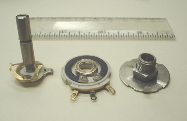
The resistance element is the dark gray arc (center) which has its ends connected between the two outside terminals. The movable contact takes the long way around. The center of the three terminals is connected to the circular metal contact inside the resistance element. On the left you see a brassy looking contact which is insulated from the metal shaft. The resistance element when turned over fits down over the shaft. The brass contact just to the right of the shaft makes contact with the metal ring which is connected to the center solder lug. The brass contact just to the left of the shaft, which is a little farther from the shaft than the one on the right, makes contact to the dark gray resistance element. As the shaft is rotated this contact touches a different part of the resistance element and causes the contact point to be connected to the center solder lug. If the pot is a linear taper, and the shaft is set half way between the two extremes, the resistance from each end of the resistance element to the center terminal will be half of the total resistance.
Linear and Audio Taper.
The taper of a pot refers to the way its resistance changes as the shaft is rotated. A linear taper pot is exactly what you would guess it to be, a graph of resistance (from one end to center) versus shaft rotation would be a straight line. If you tried to use a linear taper pot as a volume control you would be most unhappy with its performance. The sound level would go from nothing to almost full volume in about the first ten degrees of rotation and the rest would have almost no audible effect. This is because the ear responds to sound logarithmically rather than linearly. That's why sound engineers use the decibel which is a logarithmic function of power. An audio taper pot has a function which approximates a logarithmic function.The way to identify an audio taper pot is to set it to half rotation and measure from center to each end with an ohmmeter. If the resistances are approximately equal you have a linear pot. If the resistance from the counter clockwise end to center is about 10% of the total and the resistance from the clockwise end to the center is about 90% then you are holding an audio taper pot.
These are the major kinds of tapers used in home audio equipment. There are other ones but they are of little interest to us. One to look out for is the reverse audio taper. It has 10% resistance between the clockwise end and the center. This type was used as a contrast control in older black and white TV sets. Be observant when testing pots or you might be fooled.
If you are still not satisfied, here is more information about pots than you ever knew existed.
The Volume Control
The volume control is nothing more than an audio taper pot connected as a voltage divider. The circuit is shown here. When the control is fully clockwise the sliding contact (arrow in the schematic symbol) is all the way to the top of the resistor. What ever voltage is applied to the input terminals, that same voltage will appear at the output terminals.
If the pot is set to half resistance, NOT half rotation, half of its resistance is above the sliding contact and the other half is below the slider. The input voltage is always applied across the entire resistor. the voltage distributes evenly along the resistance so if the output is connected across 1/2 of the resistor the output voltage will be 1/2 of the input voltage. That applies whether the slider is set to 1/4, 1/10 or 1/100 of the resistance. Remember that 1/2 rotation is 1/10 resistance so at this setting the output voltage is 1/10 of the input voltage. 
For a verbal description click here.
The Loudness Control
The loudness control uses a special pot which has a fixed tap at 1/2 rotation. Pots for this application can easily be identified by a fourth terminal on the opposite side from the usual three.
When the control is switched on C1 connects across the top half of the pot and high frequencies are boosted above what they would normally be at the tap. C2 has a low reactance at high and mid frequencies. R1 causes high and mid frequencies to be attenuated but when the frequency is low enough the reactance of C2 will begin to rise and allow the attenuation to be less than it would otherwise be. 
For a verbal description click here.
When loudness is switched off C1 is disconnected and C2 is shorted out. R1 in combination with the resistance of the lower half of the pot gives an attenuation which is equal for all frequencies.
Pots designed for use as loudness controls usually have 1/3 of the resistance between the counter clockwise end and center. The resistance becomes 1/10 of total when the loudness network is connected. That will give a maximum of 10 dB bass boost.
Loudness, Fact or Fraud?
When listeners are tested under laboratory conditions it can be demonstrated that as the total volume decreases the base and treble must be boosted in order for the music to sound the same. This effect kicks in at moderate volume and operates from there downward. However as it is universally implemented in stereo amplifiers the loudness control works from maximum volume down to one half rotation on the control. That is, at maximum volume the frequency response is flat and as the control is rotated from there down the lows and highs begin to be boosted. At half rotation the boost is as high as it can get. Once the slider gets below half, there is no more change in the relative amplitudes of high, low and mid frequencies. On most stereos half volume is still pretty loud so the designers have it backwards. The loudness control effect should operate in the lower half of control rotation instead of in the upper half as it does. Conclusion: Fraud! I turn my loudness control off and use the bass and treble controls to get the sound I want at the particular listening level.Previous; Magnetic Phono Preamp.
Or use your "Back" button to return to where you were.
Thank you for visiting my page at Angelfire.
Please come back and visit again!This site begun March 14, 2001
This page last updated September 9, 2005.