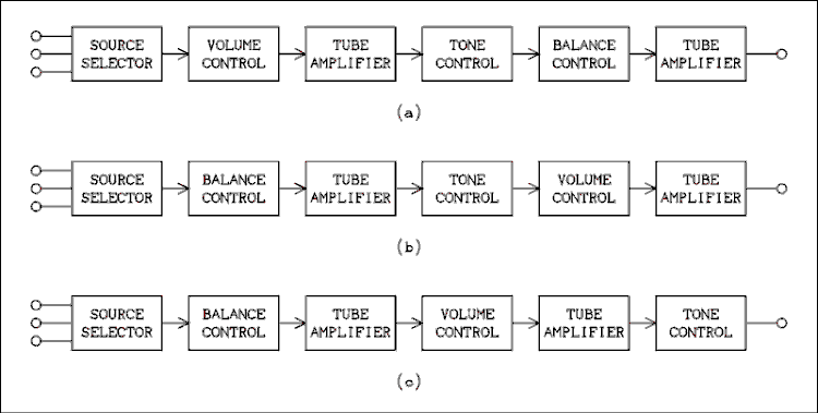
Figure 1 Three Alternative Block Diagrams of Preamp or Integrated Amplifier.
For a verbal description click here.
What is a preamp?
A preamplifier, more often known as a preamp, is the amplifier that comes before the amplifier. Makes sense, but what is it really? In an integrated amplifier it's the part where all the controls are. The source selector, volume or loudness control, balance control, tone controls and other miscellaneous controls such as rumble and scratch filters, tape monitor switching, and dubbing selectors when connections for more than one tape deck are provided, are all part of the preamp section of the amplifier.If the preamp is a separate box it has all of these controls on it plus anything else the designers could think of including level meters. The circuitry inside is pretty much the same as in an integrated amplifier. The one difference is that the output is designed to drive an interconnecting pair of shielded cables that connect to the power amplifiers. In an integrated amplifier the connection between the preamp and power amp is just a short piece of hookup wire between circuit boards.
The order of things.
It might be said that the order doesn't matter very much as long as it makes electronic sense. However a given design might make electronic sense but defies common sense such as putting the tone control before the source selector switch. That can put a lot of restrictions on things as we will see. Here are some rules of design.
- The source selector switch should be followed by a tube stage or a large value pot which is connected to a tube stage.
- A potentiometer must always be followed by a tube stage. There is one exception to this which will be covered below.
- A tone control circuit must always be preceded by a tube stage. If combining rules 2 and 3 results in two tube stages one after the other, only one is used.
- A passive tone control should be followed by a tube stage. There is one exception to this rule.
- A tape output should always be a cathode follower. The signal should be taken off before any controls that affect the tone or signal level.
- A tape monitor input should be fed in before all controls and should also be high impedance.
Here are three alternative block diagrams of preamps.

Figure 1 Three Alternative Block Diagrams of Preamp or Integrated Amplifier.
For a verbal description click here.
Rule 1.
Unless you are a fortune teller you can't predict what sources you may plug into your preamp at some time in the future. It is always best to go directly to a 500 k ohm volume control and from there to a tube stage. The volume control is preferred over the balance control because you or someone else might plug in something that has an output level that is higher than normal line level. If the volume control is first in line the signal can be reduced before it has a chance to overdrive any amplifier stages. The preceding statement becomes even stronger if you are designing and/or building a preamp for someone else.Although multiple tone controls are interesting to contemplate, you really don't want to have a separate tone control circuit for each source. Same goes for volume and balance. That's just too many knobs to put on the front of a practical preamp or integrated amplifier. The source selector always comes first.
Rule 2.
Potentiometers, pots to you and me, work as expected when the load at the wiper is equal to or greater than approximately one half the resistance of the pot. A low impedance load on a pot could cause the controlling effect to be mostly at one end. Tone control circuits, both passive and active, have input impedances which vary greatly with frequency. This would color the sound even though the controls were set flat.A pot must never be followed by another pot. The collective capacitance of two cascaded pots and the input capacitance of a tube amplifier following the second one will cause clearly audible roll off of the high frequencies. Silicon based amplifiers can get away with this because of the lower impedance and lower resistance pots that such amplifiers employ. See figures 2 and 3 below.
An exception to this rule is in the Harmon Kardon tone circuit in which the wiper of the treble control is connected directly to the balance control.
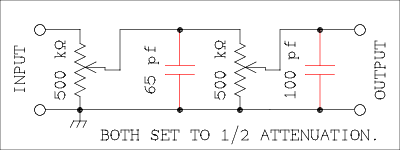
Figure 2 Diagram Showing Parasitic Capacitance Associated
With Cascaded Volume and Balance Controls.
For a verbal description click here.
The capacitors shown in red are not real capacitors but are the stray capacitance from the inner parts of the pots to the metal shell. This is approximately 30 pf for each pot. Where the first pot connects to the second it has 60 pf plus 5 pf for wiring capacitance. The output would go to a tube amplifier which would be likely to have a gain of 32. The Miller capacitance for a 12AX7 would be 56 pf. Add that to the pot's capacitance of 30 pf and you've got 86 pf. (The capacitance of 30 pf applies to each terminal of the pot.) Another 14 pf for wiring capacitance is not unreasonable.
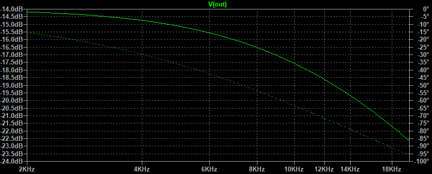
Figure 3 Graph of Frequency Response of two Cascaded 500 k ohm pots.
For a verbal description click here.
The DC attenuation of the two cascaded pots is just a shade less than 14 dB. The response is down 3 dB at a little below 9 kHz. Too much for a high fi amplifier.Rule 3.
If you look at the Practical Tone Controls page near the bottom you will see plots of the input impedance of an active circuit. Although not shown the impedance of the passive circuit shows the same excursions of impedance over the frequency spectrum. Although I made the case for driving the active tone circuit directly from the selector switch, my personal choice would be to always use a cathode follower or the Harmon Kardon arrangement .Harmon Kardon in their A-300 integrated amplifier solved the problem this way.
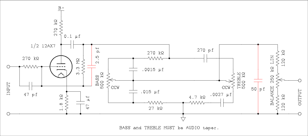
Figure 4 Diagram Showing HK tone solution showing some wiring capacitances.
For a verbal description click here.
The capacitors shown in red are not real capacitors but are the stray wiring capacitances. The input on the left comes from a 750 k ohm volume control.

Figure 5 Graph of Frequency Response of HK tone control.
For a verbal description click here.
Rule 4.
Passive tone controls work best when lightly loaded as by the grid of a tube. The one exception to this is in the Harmon Kardon arrangement, shown above, in which the balance control is connected to the output of the tone circuit. The load of the balance control was taken into account when the circuit was designed.Rule 5.
The input impedances of tape decks vary widely over different manufacturers and models. Since you never know what might be connected to the tape output jack it is wise to design for the worst case. Use a cathode follower.You don't want the setting of volume, balance, and tone, controls to affect the recording. The tape output signal should be tapped off right after the selector switch before the signal goes through any other controls or stages.
Rule 6.
The tape monitor input should be fed in immediately following the selector switch. Many amplifiers simply add another position to the switch to select the output of the tape deck. This is fine if only one tape deck is to be used with the preamp. But then there's always that unknown future. A further disadvantage to this is that a mistake in setting the controls can result in feeding the tape deck's output back into its input. That probably won't do any harm if it is caught and turned off quickly enough. However, prolonged application of an overloaded signal to the record head of a tape machine with no tape moving over the head can result in the head becoming magnetized. While heads can always be demagnetized you might not realize right away and play a valuable tape. Playing tapes with a magnetized head results in the addition of hiss and loss of highs. There is no way to recover such a tape.Simple Preamplifier, No Tape Deck.
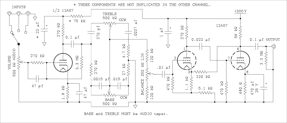
Figure 6 Simple Preamplifier.
For a verbal description click here.
This is a starter circuit. It uses 3 12AX7s, 4 pots, and a two pole rotary switch. And don't worry, a power supply will be described at the bottom of the page.This is the Harmon Kardon tone and balance circuit shown earlier. It has been compressed in size a bit so the whole schematic won't overflow your screen. The balance control is not from HK but is my own design. It may be familiar if you have read the page on balance controls under the heading Audio Amplifiers, How they Work. If you have not then it will be new to you.
The thing I have against the usual balance controls is that they are not constant volume pan. They use a special pot that has almost zero resistance over half their rotation and then the marked value from the center to the other end. Each section of the two ganged pot is the reverse of the other. This allows the balance control to have zero dB insertion loss. But if you run into a signal source that is seriously out of balance you need to use the control. Trouble is it doesn't bring up the weak channel, it knocks down the strong one. Then you have to crank up the volume to compensate. The arrangement shown brings up one channel while turning down the other. Thus it produces what is nearly a constant volume pan effect.
You will note that there is no cathode follower output. The two stages of 12AX7 have a lot of feedback around them. This lowers the output impedance and unless you are planning to put the preamp and power amplifier in separate rooms the cable capacitance should not have an adverse effect on the performance.
The 3.3 meg ohm resistor that is across the output jack is to be sure that the output capacitor becomes charged if the power is turned on with no load connected. Although we are not supposed to connect cables with power on, I have done it and I am sure you have as well. An output capacitor which has not charged up can deliver a speaker blowing 100 volt pulse to the input of your amplifier when the cable is plugged in. Five cents of prevention is worth a thousand dollars of cure.
The gain of the output gain block has been set at 33.6 according to the table on this page. The output circuit is the gain block described at that location. The preamp will have an overall gain of approximately unity when the volume control is set at about 10 o'clock. It is my belief that audio systems should be designed to give normal listening level at this setting. It leaves room to go up or down if the situation or signal level requires. An example of a situation might be "someone is trying to get the baby to go to sleep".
Although I show three positions on the source selector this decision is strictly up to the builder. It could be anything from 2 to 12. What I had in mind were FM Tuner, CD Player, and MP3 Player. Feel free to add or subtract.
Better tone control and provisions for one tape deck or computer.
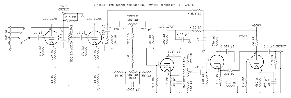
Figure 7 Quality Preamplifier.
For a verbal description click here.
This somewhat more advanced circuit uses two 12AU7s and three 12AX7s, a 4 position rotary switch and four pots.The tone circuit is figure 8 from the tone controls page. Although I made the case for putting the tone control right after the selector switch I feel it is best to use a cathode follower in between. The balance control and output gain stage have been transplanted from figure 6. The addition of a tape output adds another cathode follower. The output from the tape deck is plugged into one of the selectable inputs. This does mean that a wrong setting of controls will feed signal from the tape deck back into its input causing a terrible howl. Not only that, a very large signal fed to the record head when there is no tape running over it can magnetize the head. You could subsequently permanently damage a valuable tape by playing it on that machine. If you decide to build this version, all you can do is try to remember that you can't record from and to the tape deck at the same time.
The 3.3 meg ohm resistor that is across the output jack is to be sure that the output capacitor becomes charged if the power is turned on with no load connected. Although we are not supposed to connect cables with power on, I have done it and I am sure you have as well. An output capacitor which has not charged up can deliver a speaker blowing 100 volt pulse to the input of your amplifier when the cable is plugged in. Five cents of prevention is worth a thousand dollars of cure.
Super Preamp with Three Band Tone Control and Provisions for Two Tape Decks.
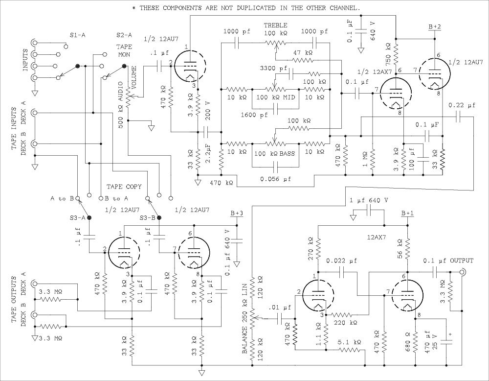
Figure 8 Super Preamplifier.
For a verbal description click here.
The diagram in figure 8 has changed. Some confusion resulted from the way I had attempted to represent the power supply connections for two channels. Figure 8 is now a diagram of one channel.So build figure 8 twice as you see it above. Then build figure 8-A once. All of this should be done in the same chassis or enclosure. The plus 300 volt point is where the external power supply connects. All points that have the same name should be connected. This includes grounds.
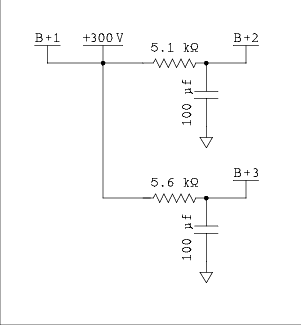
Figure 8-A Power supply connections.
For a verbal description click here.
This version has two new features: 1) a three band tone control, and 2)provision for two tape decks, or one tape deck and one computer sound card. And for good measure the tape switching is feedback proof. The circuit uses 4 12AU7s, 3 12AX7s, a 2 pole 4 or more position switch, a 2 pole 3 position switch, a 4 pole 3 position switch, and the usual pots.You may find the tape switching interesting. First, if all you want to do is listen to a tape, you select it via the tape monitor switch. When it is in position 2 you can listen to any of the sources plugged into the main inputs. When the switch is in position 1 you are listening to deck B and when in position 3, deck A is presented to the amplifier. Maybe this is backward but you can fix it when you build your own. This is independent of the Tape Copy switch which permits recording from any of the sources on the input selector. But in addition you can choose to copy a tape from deck A to deck B or from deck B to deck A.
When the tape copy switch is in position 1, which is copy deck A to deck B, The cathode follower, left, that feeds signal to deck A has its grid grounded. This is as it should be. When you are copying program material from one tape to another you don't need the confusion of another signal from the non-tape inputs. The signal that comes from deck A is fed to the right hand cathode follower and then to the deck B tape output. You can use the tape monitor switch to listen to the signal from deck A or from the third head of deck B. The setting of this switch will have no effect on the recording process. Tracing the signal from deck B to deck A is left as an exercise for the reader.
Powering up your preamp.
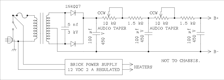
Figure 9 Simple but low ripple power supply for your preamp.
For a verbal description click here.
All three preamps operate from 300 volts for the plates and 12 volts for the heaters. However the current drain is different for each one. For the circuit of figure 6 the current draw is 6.6 mA, for figure 7 it is 16 mA, and for figure 8 it is 24 mA. And that's the reason for the pots. When both pots are adjusted to approximately the same value their dissipation is less than 1/2 watt when the voltage has been adjusted to 300 volts for the load current of the particular preamp you built. 1 watt pots are not hard to find so there shouldn't be any problem. Remember to buy audio taper pots. If you don't you will regret it.For the transformer you need a 300-0-300 volt plate winding which may be expressed as 600 VCT (volts center tapped). Both statements are describing the same transformer. Heater and rectifier filament windings are optional because they are not going to be used. AES has a few but at a rather high price. Other sites such as Triode Electronics and Tube Depot may also have them but I didn't find much in the way of specifications on either site. Just amplifier make and model replacements. Their prices were higher than AES anyway. EBay has a lot but let the buyer beware. Of course if you have one in your junk box you're in luck.
As for the heater supply BG Micro Electronics has one wall wart that is pretty inexpensive but you should test it under load before using it. MPJA has several supplies in the brick configuration. They are a bit more expensive but still in the single digit dollar amounts. They are all switching but the switching frequency is above the range of human hearing so they shouldn't cause any problems. Even if they do, filtering is possible because the supply and preamp must be on separate chasses.
The power supply should use a 3 wire line cord and plug. Ground the chassis to the green wire and you will be protected from shorts in the power transformer. Do not connect B minus to the power supply chassis. It will get its ground through the connecting cable because the B minus conductor will be grounded to the preamp chassis and it in turn will be connected to the power amplifier chassis and other components of your system.
I thought about building a voltage regulator circuit either with tubes or high voltage transistors but rejected the idea as too much complication.
This page last updated December 9, 2023. Home.