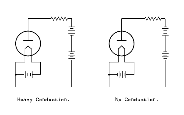
For a verbal description click here.
Figure 1Forward and reverse connection of a vacuum diode.
Electrical Fundamentals.
If you have survived "AC Circuits" you have graduated from kindergarten and are now ready for the first grade. We will start out with the simplest of tubes and then start adding grids. So lets bring it on.
Vacuum Diodes.The First Diodes.
Cold Cathodes.
The very first diodes were made by Crookes. They were glass tubes with a metal electrode in each end and a place to connect a vacuum pump. Crookes didn't remove all the air from the tube. He found that an electric arc could be maintained over a much greater distance if the pressure was reduced to somewhere in the range between 1/10 to 1/100 of atmospheric pressure. He was using voltages of thousands of volts. The only thing distinguishing the anode from the cathode was which was connected to the positive of the voltage source and which to the negative.Roentgen became curious about what would happen if the pressure was pumped down to as low as possible. He found that the arc stopped, leaving a faint greenish-blue glow. Measurements revealed that some current was flowing through the tube. The florescent material used to make watch dials glow in the dark was known in Roentgen's time and he had some in his laboratory. He happened to notice that this material glowed more brightly when the tube was in operation. He moved it closer to the tube and found that it glowed even brighter. Evidently the sample was in the form of a flat plate. Most likely it was coated on a glass plate like those used for photography in that time. When he interposed his hand between the florescent plate and the tube he probably got the shock, non electrical, of his life. He could see the outlines of the bones in his hand as shadows on the plate. That was the discovery of x-rays.
What was happening was that the strong electric field was pulling electrons out of the metal of the cathode, negative electrode, and they were being accelerated to a very high velocity and then impacting the anode. The incoming electrons had so much energy that they knocked other electrons out of the inner shells in the atoms of the anode metal. These electrons were replaced by electrons from the outer shells falling down to replace them. These large energy transitions caused the atoms to emit electro magnetic radiation of a very short wavelength, namely x-rays.
Hot Cathodes.
About this time Edison found that in a light bulb with two filaments, current would flow if the cold one was made positive with respect to the hot one but not if the polarity was reversed. He saw no use for this effect but noted it as curious.It didn't take long for Roentgen and friends to put this discovery to use. They surmised correctly that a heated filament could emit electrons better than a cold piece of metal and the hot cathode was born.
Bulbs or Tubes?
All of this was taking place before 1900. You couldn't run down to your local Radio Shack and pick up a tube. If you wanted to experiment you had to make your own. The long slender tubes that were used by chemists were readily available but they couldn't resist pressure differences as well as a sphere. When it comes to blowing a glass bulb, a sphere was easier to form than a thin tube. That's why in those old pictures the devices are usually spherical bulbs rather than tubes. In fact writings from the early years of the 20th century in the united states refer to, what we would call a tube, as a bulb.The Fleming Valve.
In England Fleming found that a device much like an x-ray tube, only much smaller, could be used to detect radio waves. It became called "The Fleming Valve" and to this day British techies and tinkerers call them electronic valves.So What's a Diode?
The name diode comes from the Greek for two. Diodes have two elements, a cathode and an anode. The simplest diodes, and likely the earliest ones, have a cathode which consists of a filament that can be heated to red or even orange hot by passing an electric current through it. The anode is a flat metal plate, often called the plate.Rectification.
Diodes can only do two basic things. These are 1) generate x-rays, and 2) rectify. Not many of us are interested in generating x-rays so let's talk about rectification.What Does a Diode Do?
The hot cathode emits electrons in droves. Many more than are needed. They build up in the volume around the cathode and form a large pool of electrons just waiting for something positive to happen. This pool of electrons is called the space charge. When the plate (anode) is made positive some of the electrons are attracted to it. They impact on it, are absorbed into the metal and electrons flow out of the plate connection into the battery or what ever provided the positive voltage. The other end of the voltage source must be connected back to the cathode in some way.If the polarity is reversed which makes the plate negative with respect to the cathode the electrons in the space charge are repelled away from the plate and no conduction takes place. The plate is cold and is made of a metal that is a very poor emitter of electrons. The voltages are not nearly as high as those used by Crooks so there is no cold emission from the plate. This makes the diode conduct current in only one direction.
For a verbal description click here.
Figure 1Forward and reverse connection of a vacuum diode.
The Space Charge.
The cathode of a tube is coated with a very special material that emits electrons very easily. It can readily be damaged by operating above or below the proper temperature or by being "poisoned" by the residual air in the tube. The space charge serves another vital function. There is no such thing as a perfect vacuum. In fact the space in near earth orbit is a better vacuum than can be made on the surface of earth. Farther out in space the vacuum is even better. What this means is there are lots of air molecules running around inside of a vacuum tube. The space charge protects the cathode from these air molecules. Some of these molecules lose an electron and become positive ions. They are attracted to the negative cathode and if it weren't for the space charge they would impact on the surface of the cathode doing considerable damage. Over time the ability of the cathode to emit electrons would be seriously impaired rendering the tube useless. As these ions run through the space charge they gain electrons from the many collisions and become negative ions. Their direction is reversed turning them away from the delicate cathode.Indirectly heated cathodes.
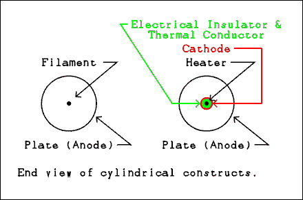
Most vacuum tubes have a basically cylindrical configuration. Figure two shows how a filament (directly heated) cathode type diode is made along with a heater type (indirectly heated) cathode type diode.
For a verbal description click here.
Figure 2 Construction of vacuum diodes.
In the filament type diode the cathode is usually a single wire running down the center of the cylindrical plate. In the heater type diode the filament is called the heater because that is its function. It is surrounded by a material which is an electrical insulator and a thermal conductor. The best known material having those properties is mica although I don't think it is used here. Outside of the electrical insulator is the cathode which is a cylinder with the special coating on the outside. The reason for having both types of tubes will be explained below.Rectification.
The most important use of diodes is as a rectifier. Rectification is the name given to the process of changing AC to DC. The process of detecting a radio signal also involves rectification. Diodes are occasionally used for clamping, preventing a voltage from going above or below a given value, or clipping, preventing an audio signal from exceeding some preset level by knocking off the peaks. But by far the most common use of diodes is as rectifiers.Figure 3 shows a directly heated cathode, filament, diode connected as a rectifier. As you can see from the wave forms this does not give the steady DC you are used to thinking of. For details about rectification and filtering see A Technical Discussion of Power Supplies in the Audio Amplifiers section of this site.
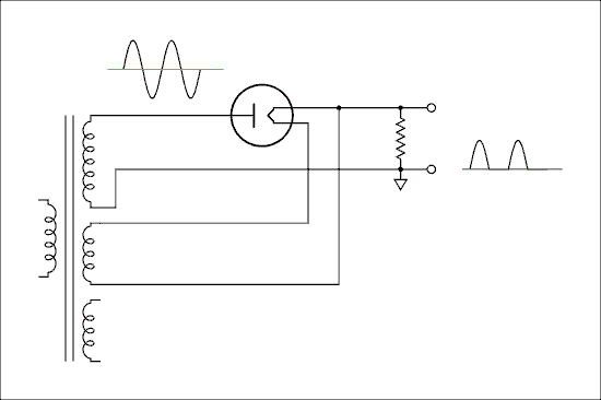
For a verbal description click here.
Figure 3 Filament type diode used as a rectifier.
The entire filament and its supply winding are at a potential of several hundred, or even several thousand, volts above ground. The typical filament supply voltage is 5 volts so the difference has little effect on the operation of the diode. When I was a novice I used to wonder why all that voltage didn't burn out the 5 volt filament. What matters to the filament is the voltage from one end of it to the other end. If one end of the filament is at 350 volts and the other end is at 355 volts the only voltage to effect the filament is the difference of 5 volts. Consider this point carefully. It's VERY important that you understand it. If you don't understand, stop and think about it. Don't go on until you do. If you need to, email a question to me. I am the teacher in this class and questions are what I'm here for.The disadvantage of a filament type rectifier, as compared to an indirectly heated cathode type, is that it requires a separate winding on the transformer or in big transmitters a separate transformer for the filament. The advantage is that the maximum voltage is limited only by the plate to filament insulation within the tube.
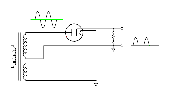
For a verbal description click here.
Figure 4 Heater type diode used as a rectifier.
Figure 4 shows an indirectly heated cathode type diode being used as a rectifier. Its heater can, and usually does, operate from the same voltage supply as the rest of the tubes in the device. Note that the heater winding is shown grounded. Also note that there is only one heater winding instead of two as in Figure 3. The insulation between the heater and cathode must withstand the full output voltage of the power supply. The best tube manufacturers were able to do was about 500 volts. Filament type diodes can be used to rectify thousands of volts.Detection
The tubes used as power supply rectifiers are not the ones you would use for detection of radio waves. In the crystal set described else where on this site you could replace the crystal diode with a small tube such as a 6AL5 or 6H6. These tubes used as detectors may be referred to as thermeonic diodes, Fleming valves, or detector tubes. But whatever they are called they work just the same.How I got hooked.
My lifelong addiction began, not with the building of a crystal set, but upon seeing an animated film on early TV showing how vacuum tubes worked. In my continuing attempts to pass on my addiction here is an animated picture showing the electrons in a diode serving as a rectifier. The voltmeter on the left is measuring the voltage of the AC input to the rectifier. The voltmeter on the right shows the pulsating DC across the load resistor. You can see the electrons in the tube being attracted to the plate when it is positive and being repelled back to the filament when the plate is negative.
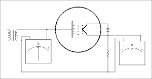
For a verbal description click here.
Figure 5 animation of a rectifier in action.
Once you have gazed upon the electrons you will never again be satisfied by transistors.
This page last updated April 17, 2004.
Home