- The Double Stick tape makes it possible to set the coil down in
mid winding and come back to it later. It won't unwind while you
take out the garbage or answer the telephone. But if your 2-year
old grandchild gets a hold of it all promises are cancelled.

- When you have wound 66 turns the last turn should be very
close to the hole at mark 1. Cut the wire about 4 inches past the
point where the last turn comes to the hole. Then pass the end
of the wire through to the inside of the tube and pull it tight.
The sticky tape will hold it in place.
- Now look at the other two spools of wire which came in the
package. One is finer than the green wire (No. 26) and the other
one is heavier (No. 22). Open the one which is heavier.
- Push about 3 inches of the wire through the hole at mark 2,
the same one where the end of the green coil goes to the inside
of the coil form. (Mailing tube.)
- Hold the end inside the tube and start winding in the direction
as if this coil were a continuation of the green coil. THIS
IS VERY IMPORTANT! The new coil MUST go as if it is a continuation of the green coil.
- Wind 3 turns and cut the wire then push the end into the hole
at mark 3 and pull it tight on the inside.- Now get 6 4-40 x 1/4 machine screws, 6 4-40 nuts and 10
number 4 solder lugs. The screws and nuts are available at any
hardware store worthy of the name. For the solder lugs you
may have to go to an electronics supply store either brick and
mortar or on line.
- Mount a solder lug on the inside and outside of the tube at
the 4 holes closest to the line of 1/16 inch holes.
- At the holes farthest from the 1/16 inch holes only mount
solder lugs on the outside of the tube. On the outside point
the lugs along the circumference of the tube and on the inside
point the lugs inwards away from the nearest end of the tube.
- Tighten all screws.
- You now have 4 wires coming through the tube to
the inside and 4 solder lugs on the inside to solder them to.
I will leave it up to you as to which wires go to which lugs.
- To prepare the end of a wire to be soldered to a lug do the following.
- Pull the end of the wire to the lug where you want it to go.
- Leave quite a bit of slack in case you break the wire before you solder it.
- Cut off the excess and bring the end of the wire out of the end
of the tube so you can get at it.- Tare off a small piece of sand paper about 1 inch by 1/2 inch.
Fold it in the middle of the long dimension with the sand on the inside.- Place the end of the wire inside the sand paper, pinch it
between thumb and for-finger and pull it along the wire to
its end. Work on the green wire first. You will see the
green enamel come off and the copper wire underneath
will be revealed. Work around the wire until there is a
bright copper area at the end of the wire.- The heavier wire may not look like it is enameled but it is. You
will see a change in color as you work on it with the sand paper.
- Pass the end of the wire through a hole in a solder lug on the
inside of the tube, wrap it around and solder it in place.
- Do this for all 4 wires.
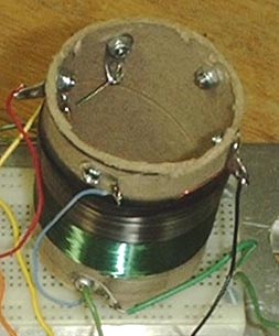
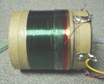
- The picture shows the solder lugs. The third winding of
the finest gauge wire from the pack is covered by electrical
tape. Also I DO know how to count, as you can see in the
picture I put the sixth lug at the other end of the coil
form but I would do it differently the next time.
- Now you will add one more winding to the coil. Wrap one turn of
Double Stick tape around the coil where the two coils come together.
The tape should cover the first turn of the copper colored winding and
most of the width should cover part of the green winding.
- Now open the third spool of wire from the Radio Shack package of
wire. This is the finest gauge wire.
- Remove the enamel from the end and solder it to one of the two
remaining solder lugs that does not have a wire connected to the
inside. Most solder lugs have two holes, solder the wire to
the lower hole (closest to the screw.)
- Angle the wire over to the place where the green and copper coils
come together and begin winding there. Wind this coil over the
green winding. Wind about 6 - 1/2 turns.
- At the end of the coil angle the wire back over the winding to
the remaining solder lug.
- Cut the wire to the proper length and remove the
enamel from the end.
- Solder the wire to the lower hole in the solder lug.
- Make sure the wire is securely stuck to the tape.
- Wrap a layer of conventional tape over the winding you just
put in place. I recommend vinyl electrical tape because it
has some ability to stretch and can be wrapped tightly.- Now solder lengths of colored insulated hookup wire to
the lugs on the coil form as follows.
- Yellow wire to the end of the green coil
coming through hole at mark 2.- Green wire to the end of the green coil
coming through hole at mark 1.- Red wire to the end of the heavy 3-turn
coil coming through hole at mark 2.- Blue wire to the end of the heavy 3-turn
coil coming through hole at mark 3.- Black wire to the end of the fine 6 - 1/2 turn
coil closest to the heavy 3-turn coil.- White wire to the end of the fine 6 - 1/2 turn
coil farthest from the heavy 3-turn coil.This completes the antenna coil. Now, that didn't hurt a bit did it!
The colors for the wires were not selected on a personal whim. Traditionally in tube equipment certain wire colors have been associated with certain functions. General signal carrying wires are white, ground wires are black, B+ or plate supply wires are red, wires from plate coils to the plate of a tube are blue, wires from grid coils to the grid are green, and wires to the opposite end of grid coils are yellow. These last may supply grid bias or AGC/AVC (Automatic Gain Control/Automatic Volume Control).
This page last updated May 17, 2002