
1950 version of the grid dip meter.
For a verbal description click here.
The grid dip meter or grid dip oscillator has been used by hams for decades to measure the frequency of resonant circuits and antennas. It can do the job normally done by more expensive equipment although it is not as accurate as expensive laboratory instruments. I believe that modern day electronics tinkerers don't fully appreciate what they consider to be an old fashioned device.History.
The principle of the grid dip meter was developed in the 1920s. Wikipedia was not more specific than that. If anyone has more information I would appreciate it if you would send it along to me.The first appearance of a grid dip meter in the ARRL Radio Amateur's Handbook was in the 1948 edition. It is called a "Test Oscillator and Grid Dip Meter" but it is barely recognizable. It is an oscillator configuration I am unfamiliar with. A 6SN7 is configured as a cathode follower driving a grounded grid amplifier which makes a noninverting amplifier. The plug in coils have two windings. This circuit was repeated in the 1949 edition but in 1950 the circuit shown below appeared.
1950 version of the grid dip meter.
For a verbal description click here.
The 955 is an acorn tube. When operated at a plate voltage of 135 volts its amplification factor is 25, its plate resistance is 13,200 ohms, and its transconductance is 1900 micro mhos. This circuit appeared for the next two years and in 1953 was replaced by the circuit shown below.

1953 version of the grid dip meter.
For a verbal description click here.
The 6C4 has two pins connected to the plate which results in a shape that may make you think of a heater. The first time I saw it I was very confused. The 6C4 was quite a modern tube in 1953. This circuit ran through 1961 and in the 1962 edition the circuit below appeared.

1962 version of the grid dip meter.
For a verbal description click here
The very new Nuvistor was used in this version. It was ideal for a GDM because of its small size being only about twice as big as a TO-5 transistor. It lasted at least until the bicentennial year of 1976. I don't have any editions of the handbook after that so I can't say when it was replaced by an all transistor version.
Want to Build One?
The transformer is one of those simple transformers that has two secondaries, one with a voltage of 125 volts at either 25 or 50 mA, and the other 6.3 V at 600 mA or 1.2 A.The entire circuit can be built into a single enclosure as many commercial GDOs of the tube era were. It can also be separated into two units with the oscillator in one section and the power supply and meter in the other. This is the significance of the dashed line in the schematic. The Nuvistor version would benefit most from this treatment.
Also another handbook version used a transistor as a meter amplifier for increased sensitivity. The metering circuit used a 1.5 volt cell for power and it had a separate on/off switch. That's a recipe for a run down cell on a Saturday afternoon with a project underway and no replacement on hand.
Once in a QSO a ham described a GDM he had brewed up. He had fastened the frequency scale to the coil so when a coil was plugged into the meter the proper frequency scale was in place and there was never any confusion or errors caused by reading the wrong scale, something I have done, how about you?
The question of tube versus transistor is relevant. Although I like to build tube circuits when I build a piece of test equipment I prefer the small size and low power consumption of transistor and IC devices. You may want to find an ARRL handbook new enough to have a transistorized dipper. Avoid any circuits similar to the Heathkit tunnel dipper. The meter deflection is small and the dip is right on the edge of being imperceptible. The Millen type 90652 "Solid State Dipper", pictured at left below, uses a 3N128 duo gate MOSFET as the oscillator device. There is also a meter amplifier using BJTs. It operates from a 9 volt transistor radio battery.
A transistorized dipper is fine as long as you confine your dipping to indoors. If you want to use it for antenna adjustments with an antenna bridge such as the Millen type 90672 pictured at right below, you may find the RF level from the dipper to be inadequate. In this case I would advise constructing a true grid dip meter employing a tube.
If you like to build historically accurate reproductions of old equipment you may want to go for the 1950 circuit. 955s are likely to be hard but not impossible to find. Failing that your choices are between the 1953 and 1962 circuits. Nuvistors are not hard to find but the sockets may be another story. If you can find a socket this is probably the best choice. I suspect that most will go for the 1953 circuit. The 6C4 is easy to find and so is a socket. It has another advantage in that the tuning capacitor is a simple single section one. The drawback is that the coils need three contacts. Probably the easiest connector to find is the European DIN plug and socket. Although this was not designed for RF use it is easy to find. The 1962 version only needs two contacts for the coil. Each coil can be mounted on an RCA phono plug and an RCA socket mounted on the dipper enclosure. The shell must be insulated from the chassis because both sides of the coil are hot.
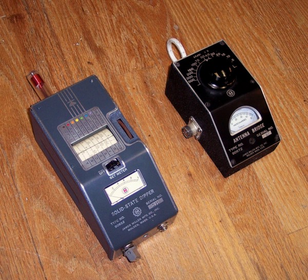
Millen Solid State Dipper and Antenna Bridge.
Theory of Operation.
The theory of operation is very simple. The oscillator coil on the GDO is outside the enclosure and is its probe. When this probe is brought into close proximity to a tuned circuit which is resonant to the frequency to which the GDO is set some energy is taken from the oscillator causing a decrease in amplitude. This decrease is indicated by a decrease in tube grid current which is monitored by a current meter. As the GDO's frequency is tuned across the frequency of the tuned circuit under test a dip in grid current is observed, hence the name.Operation.
My first encounter with a GDM was unsuccessful because of my impatience and high expectations. I expected the meter to drop from half scale to near zero. Furthermore I was turning the frequency knob much too fast.
Operating Procedure.
- Select the coil that covers the range of frequencies you are interested in.
- Plug the coil into the GDM.
- Adjust the meter sensitivity control for a reading of ˝ to 1/3 scale.
- While holding the meter away from the test circuit and any metal parts, rotate the frequency knob over its entire range to make sure it doesn't go off scale.
- If it does go off scale decrease the sensitivity until it doesn't.
- Also note the points where the current is at a maximum and minimum so you won't be fooled by a dip that is part of the instrument's nature.
- Place the GDM's coil in close proximity to the circuit under test with the axes of the two coils parallel.
- SLOWLY tune the frequency of the GDM until you observe a small dip in current that wasn't there when the meter was in open air. The dip can be quite subtle and can easily be missed if the frequency is tuned too fast or you are not attentive to the meter indication.
- Read the frequency from the proper scale.
That's really all there is to it.
This page last updated August 23, 2014.