For a verbal description click here.
One Tube Radios
Grid Leak Detector.
The first urban legend I ever heard has it that some pieces of world war two electronics equipment contain little trays which were listed on the parts manifest as "Drip pans for grid leaks". Personally, I doubt it. The most likely explanation is that there were some interference shields that someone with a sense of humor started calling "Drip pans for grid leaks". Once the story got started it couldn't be stopped. If tubes were still in wide use the story would likely be around today. This may even have been the very first urban legend. Grid leak refers to the charge on the grid of a tube leaking off through a resistor.In these modern times it's not easy to find parts. Some of you may be afraid of winding coils (it took me many years to get over helixaphobia. However my investigations have led me to the inescapable conclusion that winding coils is the best way.
It's really not that hard and it is guaranteed to be painless. I have devised a method in which you use Double Stick (stickem on both sides) Scotch Tape to hold the wire in place while you wind the coil. One of the most frustrating things about winding a coil is what happens when you let go of it. The double stick tape prevents this from happening. To learn how to wind your own coils click here.That's what I thought three years ago. I have found that some of the old coil sets are still available. The P-C70-A from Antique Electronics Supply works just as well and maybe a little better than the coils you can wind. Winding coils is an interesting experiment and you may want to do it just for the fun of it. If you would rather skip all the fun you can. Some additional instructions have been added below.
If you don't have a variable capacitor you will need to buy one. If you would rather not wind your own coils there are ferrite antennas and antenna coils for sail. Click here to learn what to buy and where to buy it.
Another source is to take a transistor radio apart to salvage the tuning capacitor and ferrite antenna. It's kind of fun tearing up one of those disgusting little things and you might learn a thing or two in the process. The parts you get are of limited usefulness which is why I really don't recommend it. If you have the time and the inclination give it a try. Just click here.
This circuit is probably called what it is because in the very earliest days of tube radios the resistor which connected between the grid and ground was called a "grid leak". The 2.7 Meg Ohm resistor is the grid leak in this circuit.
All AM detectors whatever they may be called or what or how many components they use are based on the principle of rectification and filtering. The Grid Leak Detector uses the grid of the tube as the anode of a rectifying diode for this purpose.
Normally the grid of a tube is negative and so it repels electrons but if the grid goes positive it will attract electrons to its self. The grid wires are fine and fairly far apart but even so some electrons will impact it especially when it is attracting them. This causes a current to flow like the forward current through a diode. The cathode of the tube is grounded and the signal is applied to the grid where it is rectified. Here is the circuit of the Grid Leak Detector.
For a verbal description click here.
I have had inquiries about how these one tube radio circuits work with 12 volt car radio tubes. I can say that this one works quite well thank you. It's not quite a plug and play but a few component value changes will have you listening to local stations with no danger of being shocked.
For a verbal description click here.
Remember that if there is NO DOT where two lines cross there is no connection there, they just cross. A dot means there IS a connection.
If you are using the Hammond antenna coil from AES connect it as follows. Pins 2 and 4 to ground. Pin 1 to the tuning capacitor and RC grid leak. Pin 3 to the antenna. This runs counter to the connections recommended by the manufacturer but I know what I am doing. Try connecting a 33 pf capacitor between pins 1 and 3. Refer to the Crystal Set article. See how the performance changes with and without the capacitor.
You can also use this circuit with modern stereo headphones by connecting the primary of a 10 k ohm to 2 k ohm audio transformer in parallel with the 4.7 meg ohm resistor. Also see the Crystal Set article referred to above.
The wire antenna and ground induce magnetic fields in the ferrite rod for each radio station in your local area. The large winding of the ferrite antenna is tuned by the capacitor to one of the station's frequencies. The voltage of the carrier wave is applied to the grid of the 6AU6 tube through the capacitor and grid leak resistor.
When the voltage swings positive there is current between grid and cathode which charges the capacitor. The capacitor is charged up to the peak voltage and very little of this charge leaks off before the next peak recharges it. The average voltage applied to the grid is negative. The larger the voltage the more negative is the grid. The charge on the capacitor can change quickly enough to follow the waves of the modulation. The average negative voltage applied to the grid is proportional to the modulating signal. This causes variations in plate current which also follow the modulation. There are also variations in plate current which follow the carrier frequency but they do not produce any significant output voltage because the capacitor from plate to ground filters them out. The output from the plate is the recovered modulation which has been amplified by the tube.
To sum it up the grid-cathode circuit rectifies or detects the signal and the entire tube amplifies the recovered audio.
The circuit is constructed on the "Practical Breadboard for Tube Circuits". Set the power supply to 150 volts.
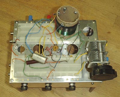
We have left the transistor radio components behind and move to more suitable devises. The tuning capacitor is from a real AM radio and the large ferrite antenna is of the type used in large portable (as opposed to pocket sized) and table model transistor radios. This type of antenna may have been used in some late model tube radios but I have never seen one.
The antenna has two windings, one covers almost all of the rod and the other is a few turns at one end. The windings usually are wound with two different colors of wire. The large winding connects to the tuning capacitor and through the R and C to the grid of the 6AU6. Be sure to ground the end of the large winding which is closest to the small winding.
The screen grid of the tube goes to the wiper of one of the 100 k ohm pots in the breadboard. There is an optimum voltage for the screen which is about at 10:30 on the control's rotation. The sound will be loudest at the best setting.
Have fun and remember to turn off the power before sticking your fingers into the circuit. Unlike the voltages found in transistor radios these voltages can really give you a shock.
If you're having trouble understanding the explanations on this page try How a Vacuum Tube Works.
This page last updated June 23, 2011.