The other page on making IF transformers, click here, Is intended for new construction and if that is what you need I recommend you go to that page. However, if you have an AA5 or similar old radio you want to restore to operation and you are absolutely convinced that one of the IF transformers is defective you are reading the correct page.Spoiler alert. Yes, it can be done.
What you can replace and what you can't.
All prewar and wartime radios have the large IF transformers that are usually associated with octal tubes. Very roughly 5 years after the end of the war AA5 radios transitioned to the use of miniature tubes and a much more compact IF transformer. The large and small kind are shown together below.
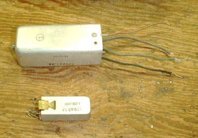
Figure 1 Older, Large, and newer, Smaller, IF Cans used in AA5 Radios.
The larger one which is 3-1/2 inches long and more importantly 1-1/4 inch on a side is large enough to squeeze in two of the transistor IF transformers and the circuit board to mount and connect to them. I don't at present see how this could be done for the smaller one. I'm a little tired of looking at this problem at the moment. Maybe in a few weeks or months I can come back to it with a fresh perspective and crack the problem.
Is that transformer really bad?
IF transformers are quite reliable and aside from a lightning strike or a cooked coil caused by a shorted tube there isn't much that can go wrong with them.So, suppose you have diagnosed one with an open coil. First make a drawing or take a picture, or maybe both, of the radio chassis showing where each wire from the IF transformer connects.
Then unsolder all four wires. If there are more than 4, is this an AM radio?
Remove the nuts and washers from the screws that hold the transformer in place.
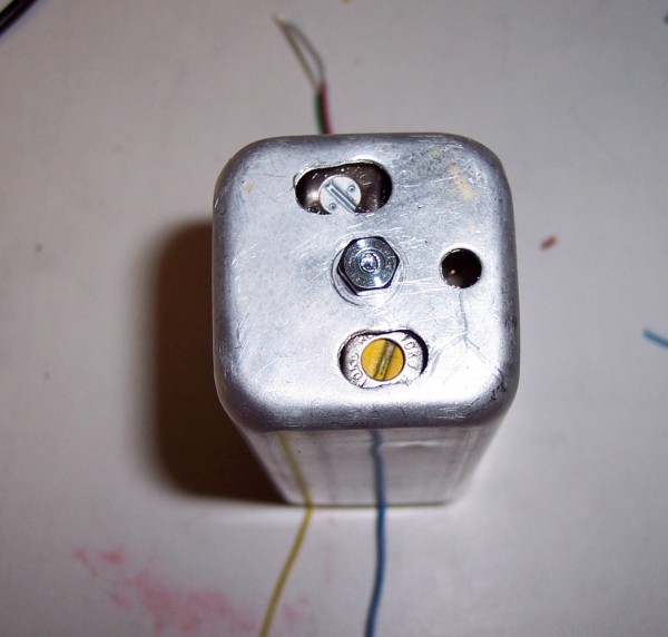
On top of the can are the two holes that give access to the adjustment screws and a cap nut. Remove the nut.
The innards of the transformer may easily slide out of the can but after more than 65 years don't count on it.
If the end of the screw that the nut came off of is still sticking through the hole in the can tap it gently on your workbench until it is forced back into the can. Now maybe it will come out. Do not pull on the wires or the bottom end of the cylinder.
Use a screw or thin screwdriver to push the screw deeper into the can. Remember, there is still a possibility that this transformer can be repaired so don't destroy it trying to get it out of the can.
Let's assume that by the use of gentle persuasion you have succeeded in getting the transformer out of the can intact. Here is what it should look like.
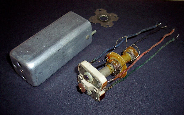
Figure 2 Old Style IF Transformer out of its can.
The ceramic block at the top contains two compression mica trimmer capacitors which tune the coils to resonance. Note that the wires that go to the rest of the radio circuit are soldered onto the lugs of the trimmers along with the fine wires from the coils. Inspect the fine wires carefully to see if any are broken.
If one of them has broken it should be only one so there won't be any doubt as to where it goes. More than likely the coil is wound with Litz wire. This is a wire made up of several finer wires that are insulated from each other by an enamel coating. First remove any cotton thread that might be covering the wire. Then separate the individual wires and use a piece of fine sandpaper to remove the enamel coating. Stick the sandpaper to your thumb and forefinger with double sided tape. This way you can open the folded paper after you pull the wire from between the two sides and close on it again for another pull. Do I need to say, be careful not to break the wire from the coil while removing the insulation. Clean out the lug with solder wick and solder the wire to it again.
If there is not enough wire to reach from the coil to the lug solder a piece of number 22 bear wire to the lug. Then bend a loop in the end of the wire and solder the wire from the coil to it.
Make a continuity test and if all is well reinstall the transformer in the radio, resolder the leads and thank your lucky stars that you didn't have to make a new transformer.
Making an IF Transformer out of two transistor IF transformers.
All you need of the old transformer is the can. If you are a saver I don't need to tell you to save the trimmer capacitors and one good coil. If you are not a saver I don't need to tell you to throw them away. But if you do, you will need them for another project next week.Now I suggest you go to the other page about making IF transformers where you can read about the research that went into the making of this one. That way I don't have to type it all again. I could just copy and paste but what would be the point. Come back here when you are finished.
Now that you have seen the schematic diagram and scope traces of frequency sweeps of the transformers we will get on with building them.
Parts List.
Quantities are for two transformers. Quant. Part # Description & Link Vendor & URL 2 sets ACS1667 Set of 3 AM IF transformer, yellow, white, and black.
Go to pageBG Micro Electronics
http://www.bgmicro.com/1 22-508 Prototyping Board
Go to pageJameco Electronics
http://www.jameco.com2 338-1042-ND 100 pf silver mica capacitor
Go to pageDigiKey
http://www.digikey.com/2 4-40 x 1-1/4" machine screw Local Hardware Store 10 4-40 x 1/4" nut Local Hardware Store 2 #4 insulating washer Local Hardware Store 2 Empty IF Cans From radio under repair Construction.
The first step is to cut the printed circuit boards but before you can do that you must build two cutting sleds for your band saw. Here is a picture of the two.A Little, No a Lot of Woodworking.
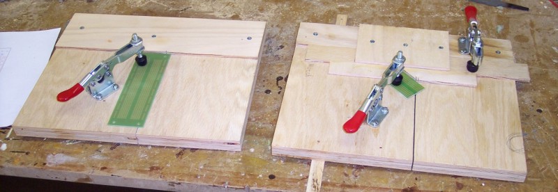
Figure 3 Two cutting sleds for band saw.
The one on the left is for making right angle cuts. The PC board that is clamped in place is shown in a position for a cut that is not made for this project. The one on the right is for making 45 degree angle cuts.
Start by making two strips of hardwood such as oak that will fit into the miter slot of your band saw. They should be 10-1/2 inches long. They need to make a snug but not tight fit in the slot. When in the slot they should be even with or a scoash below the surface of the table. How you make these will depend on what tools you have available. These will be known as the guides.
Cut two pieces of 3/4 inch plywood that are 9-1/2 by 11-1/2. These should be reasonably square although if they are a little off they will effect only the appearance of the final product. These will be known as the bases of the sleds.
Place one of the guides in the miter slot and position one of the bases on the table with the long dimension perpendicular to the miter slot. Adjust the position so the blade is in the center of the long dimension. If the base is not overhanging the back of the table move it back so it is. Then precede with the next paragraph.
If the back edge of the base is already hanging over the back of the table slide the guide towards you so its back end lines up with the back of the base.
Note: I am assuming that you are standing where the operator normally stands looking along the miter slot with the teeth of the blade toward you. The back of something is toward you. The front is away from you and when you push work through the saw you push it forward toward the front of the table.
Clamp the base to the table and the guide to the base. Leave room enough so you can drill a hole from underneath up through the guide and part way through the base. After everything is clamped drill the hole that is the proper size to be a pilot hole for the flathead screw you are going to use.
Remove the clamps and everything from the band saw table. Place the base upside down on your workbench and the guide beside it. Enlarge the hole in the guide to be a clearance hole for the screw. Then drill a countersink for the screw. The guide isn't very thick so be careful not to go too far. The head of the screw should be just flush with the surface of the guide. Fasten the guide to the base with the screw.
Use a square to adjust the guide to be perpendicular to the back edge of the base. Drill a pilot hole through the guide and part way through the base near the front. Drill a clearance hole just through the guide and also a countersink. Fasten the guide to the base at this end.
In the same way install two or three screws more or less evenly spaced along the guide.
Place the sled on your band saw table. It should glide smoothly in the miter slot. If it does not, move it back and forth vigorously several times. The metal will leave marks on the wood where it is rubbing with pressure. Lift up the sled and note where the marks are. Plane down the high spots that are indicated by the marks. Be careful not to go too far. Note: If you don't have an edge plane in your shop you may have to remove the guide from the base to accomplish this.
Measure 3 inches from the back of the sled along the line that the blade will cut and make a mark. Turn on your saw and cut to this mark. IMPORTANT: Band saw blades tend to drift when making long cuts. Make this cut slowly using a two steps forward, one step back motion. Cut a very short distance then back up allowing the blade to correct any drift. This is very important. If the blade drifts during this cut the sled will be worthless.
Remove the sled from the band saw table. Cut an 11-1/2 x 3 inch piece of 1/4 inch plywood. This will be known as the fence.
Place this piece on the back of the base on top. Line up the edges but don't fasten it down as yet. Now use the most accurate square you have to adjust the front edge of the fence To be perpendicular to the slot you cut in the base. I cannot overemphasize the importance of this adjustment. If after the adjustment the back edge of the fence is overhanging the back edge of the base push the fence forward until there is no overhang. Check the squareness again and drill a hole at one end of the fence. Install a screw and tighten it down.
Once more check for squareness and clamp the other end of the fence. Drill and install another screw at the other end. Install another screw near the center of the fence but not in line with the kerf, that's what the slot is called that the blade cut. Sometime you might accidentally push the sled all the way through the saw. That will ruin the sled but if the screw is not where the blade will hit it at least you won't ruin a blade at the same time.
Using the other guide and base make another sled in exactly the same way.
Making the 45 degree jig.
Cut a 1-1/4 by 10-1/2 piece of 1/4 inch plywood.Next you need to cut a 4 inch square of 1/4 inch plywood. This needs to be as accurate as you can make it. You can use one of the sleds you just made to make the cuts on your band saw or you can use your table saw. Use which ever one you feel most comfortable with. If using the band saw remember that the harder you push on the work the more blade drift you will get. You don't want to widen the kerf in either of the sleds you just made so if you use one push gently and let the saw do the work. Also using the two steps forward and one step back method won't hurt either.
Now that you have a square of plywood you can make two triangles out of it by cutting along a diagonal. You can do this using one of the sleds but first you need to mount one of the toggle clamps to a sled.
With the saw turned off slide a sled across the table so the blade passes through the kerf. Position the clamp so the head comes down a little more than 3 inches from the edge of the fence but does not interfere with the band saw's upper guide when the sled is pushed across the table. Do not raise the upper guide to clear the clamp. The upper guide must remain set as low as possible to obtain the best cut. This is not the permanent position of the toggle clamp. It will have to be moved to use the sled to cut circuit board.
Hold the sled up to the light and adjust the position of the square so you can see both corners centered in the kerf. Clamp it in place. Place the sled back on the saw table and cut the square in half.
You now have two perfect triangles. When you set one on top of the other they should be exactly the same in all dimensions.
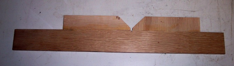
Figure 4 Forty Five Degree Angle Jig.
The long piece in the picture is the 1-1/4 by 10-1/2 piece cut earlier and the two pieces with 45 degree ends are what's left of the two triangles after being cut down to 1 inch wide. Nick a little off the sharp end of each angled piece. The reason for this will be explained below.
Find a piece of scrap that the three pieces will sit on. Ask your wife for a piece of waxed paper and place it between the scrap and the three pieces of plywood. Apply glue to the edges of the angled pieces, the edge which goes against the long edge. Apply it with your finger. Don't use too much. It takes 6 clamps to do this glue up. Two on the long piece, one at each end, and one on each angled piece.
Clamp the long piece to the scrap and position the two angled pieces as in the picture. Place them in the approximate center. Loosely clamp each angled piece to the scrap board. Push the joint closed making sure that the waxed paper is not folded and pushed up between the two pieces of wood. Tighten the clamps a little.
Now put two more clamps, one to hold each angled piece against the long piece. Do not put so much force on these clamps that the pieces warp and become miss aligned. Let the glue dry overnight.
Next day remove the clamps and inspect your work. If there is any miss alignment between the pieces, sand them down until the surface is flat.
In my case the angle jig was a little warped and when laid on the sled it either raised up on both ends or in the middle depending on which side was down. This is a common occurrence with thin plywood and it is likely to happen to you.
Cut a 5 by 3-1/4 inch piece of 1/4 inch plywood.
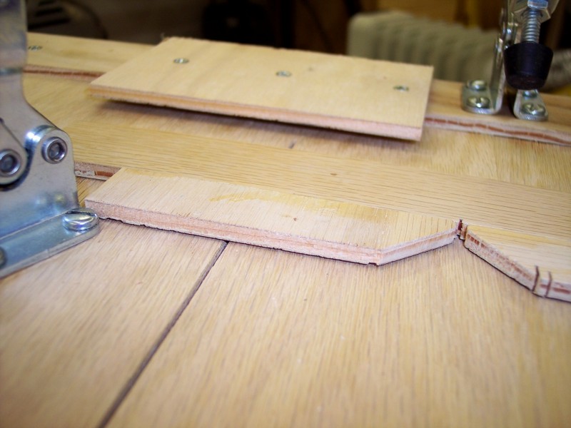
Figure 5 Hold Down for Angled Jig.
Mount it to the fence of the sled as shown in the photograph. Be sure the screws do not run into the screws that hold the fence to the base. Also do not place the center screw in line with the saw kerf.
The purpose of this piece is to hold down the center of the angle jig when it tries to rare up. Apply paste wax to both surfaces of the angle jig so it will slide more easily.
Mount a toggle clamp to the fence to hold the angle jig in place during use.
This completes the cutting sleds and jig.
Using what you just made to cut printed circuit boards.
Believe it or not a slightly dull blade is better for cutting glass epoxy PC board than a new one. That means you don't have to waste a new blade for this purpose. So get out that old dull blade that you just couldn't bring yourself to throw away and put it on your saw.First we start with the circuit board as it comes from Jameco.
Figure 6 First Cuts On PC Board.
We start with the right angle sled. That's the simplest one. The first cut to make is the one between columns 1 and 2. When using this sled the keeper piece, called the work piece by woodworkers, is to the right of the kerf.
mounting the toggle clamp.
Place the sled on your workbench with the open end of the kerf away from you. Lay the PC board on the sled with column 1 on the left and higher numbered columns to the right. Push it back against the fence.Position the toggle clamp to the right of the kerf so the head comes down on the circuit board. Drill a hole and mount the clamp to the base with a single screw.
Remove the PC board and place the clamp on your band saw's table. Push it through an imaginary cut with the motor turned off. Make sure the clamp does not come in contact with the upper guide or any other part of the saw. If there is a considerable distance between the clamp and parts of the saw rotate it about the mounting screw until it comes close without touching.
Set the PC board back on the sled and verify that the head of the clamp still comes down on the board. If it does not, move the sled back to your workbench, reposition the clamp, and drill a new mounting hole. Check again for interference with the saw and if the position of the clamp is good drill and install the remaining three screws.
Making the Cut. I'll bet you thought we'd never get here.
Line up the holes in column 1 with the kerf. Hold the sled up to the light and push the PC board to the right until the right edge of the kerf begins to cut off light on the right side of the holes. Don't go as far as making them appear as half-moons. Just a little on the right. Snap the clamp down, put the sled on your saw and turn on the power. Gently push the sled and PC board through the blade letting the saw do the work.The next cut you want to make is between columns 16 and 17. Turn the PC board around so the keeper piece is on the right. Line up the holes in column 17 as before. Close the clamp and make the cut.
If you want to make two transformers you need to repeat this procedure.
Figure 7 Forty Five Degree Angle Cuts.
Now is a good time to drill the hole at the center of the board between holes E9 and F9. Use a 1/16 inch bit for the initial hole and enlarge it to 7/64. This will be the mounting hole for the board.
Remove the square cut sled from your saw and find the 45 degree angle cut sled. I think it will be easier to set the cut position if you have a view of the cut plan viewed at the same angle as you are actually seeing the board.
Figure 8 Figure 7 rotated by 45 degrees.
Lay a straight edge on your computer screen and start counting vertical columns of holes from the center hole you drilled earlier. The column containing the mounting hole is zero. Moving to the left you will count 1 - 2 - 3 - 4 - 5 - 6 - 7. Just outside column 7 is the cut line. Column 8 is outside the cut line which means it will be cut off.
Place the circuit board in the triangular cutting jig in the same orientation as shown in Figure 8. The board should be foil side down. Make sure that the board goes into the jig and does not move back and forth. The open corner in the jig is so small particles from cutting will not prevent the corner of the board from setting all the way into the V shaped jig. If there is some wiggle remove the jig from the sled and file down any high spots that are keeping the board from going all the way into the V.
Slide the jig and board until the drilled hole is over the kerf. Then slide the jig and board to the right together while counting as you did on the computer screen. Don't forget that the drilled hole is at column zero and one comes after zero.
When you see light through the holes in column 8 you are almost there. Be sure the jig is tight against the fence and the board is firmly in place in the cutout. Line up the board so the holes are centered over the kerf. Snap the toggle clamp.
Now mount the other toggle clamp on the right side of the sled so it will hold the small piece of PC board in place. Check for interference with the saw and when you have the clamp properly positioned drill all four holes and mount it to the board.
Again line up the PC board, clamp it to the sled, and make the cut.
Release the clamp holding the circuit board and rotate it 180 degrees without turning it over. Fit it into the jig and close the clamp. You shouldn't need to count columns but you can if you want to. If all looks right make the cut.
You now have two parallel edges cut on the board. Return to the right angle sled and place one of the newly cut edges against the fence. Line up column 8 of holes over the kerf and clamp the board to the sled. Make the cut. Turn the board around 180 degrees and again line up column 8. Clamp the board and make the cut.
If you are making two boards repeat the above for the other board.
This completes the process of making the PC boards.
One More Little Thing.
That little thing is a piece of 1/4 inch plywood that keeps the PC board from shifting as pressure is put on it by the alignment tool. I don't know exactly what to call it. You can see it in the pictures below
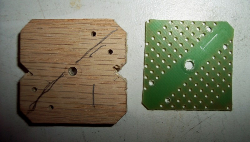
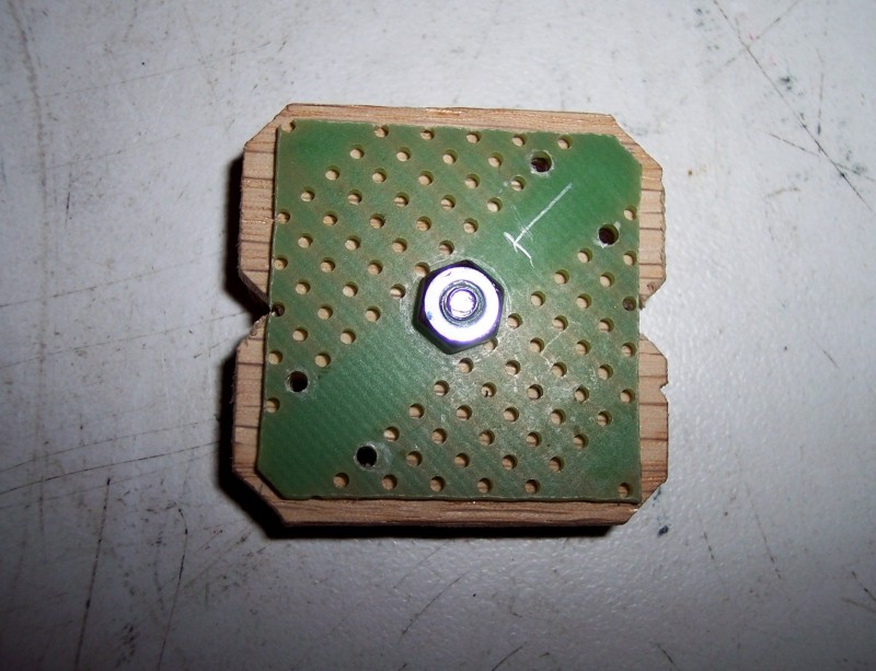
Figure 9 Plywood Spacer and PC board.
You can make the spacer, for lack of a better name, out of almost anything. Poly carbonate might be a good choice but a bit on the pricy side. Hard board commonly known as Masonite would also work as well as aluminum.
Cut two squares of your chosen material that are 1-5/16 on a side.
Mark the diagonals and where they cross drill a 7/64 inch hole.
Nick off the sharp corners to accommodate the rounded corners of the IF can. Make cutouts in each side by whatever means you can. These are to allow the piece to be inserted into the can past the mounting screws.
On the PC board use a pencil to draw a circle around each of the following holes. E4, F4, E14, and F14.
Mark the spacer and PC board so you can identify them and get them back together in the same way later. Temporarily fasten the PC board and spacer together with a 4-40 x 1/2 screw and nut.
Using a 1/16 inch bit enlarge the marked holes on the PC board and drill through the spacer. Note: These holes had already been drilled when the pictures were taken.
Remove the 1/2 inch screws and separate the boards and spacers.
Insert a 4-40 x 1-1/4 screw through the hole in the spacer from the side that will be facing away from the PC board. Thread a nut on the screw and tighten it firmly.
Do the same for the other spacer.
Set the spacers aside until they are called for.
Here's the Deal.
I'll make the same deal on this page that I made on the other one. You must order the prototyping board from Jameco and send it to me in a business sized envelope. Tell me which type of transformer you are making. I will return the cut boards along with the large offcut from the right end of the board by first class mail. I require this to discourage people from thinking "I might need a couple of those someday so I think I'll ask him for them. Please don't ask unless you have an immediate need.I'll also make the spacers out of 1/4 inch plywood unless you specifically ask me not to. You might find it a bit difficult to get a 4' x 8' sheet of plywood into a first class envelope, so don't even try.
Modifying a tool for this project.
In the final assembly of this project you have to tighten a 1/4 inch nut between the two transistor IF transformers that are mounted on the PC board. The spacing is too tight for a standard nut driver. If you have a driver made for tight spaces you are in luck. If not you will have to grind down a conventional one.This is never recommended by the manufacturer because it weakens the wall of the driver and if someone puts a lot of muscle on it the driver can break. I had a number of choices and the one I selected was the 1/4 inch stubby from a set with many driver bits and two handles. The stubby bit combined with the stubby handle is intended for use in a tight space. Working in such a space it would be difficult to generate a lot of torque so damaging a modified tool seems unlikely.
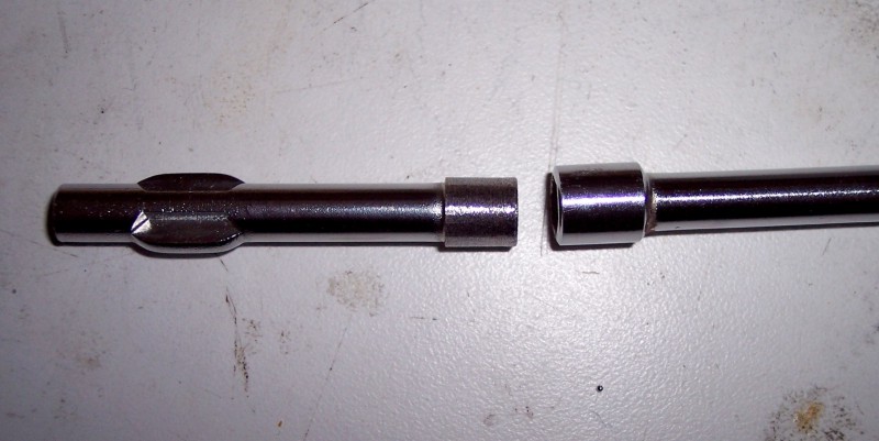
Figure 10 Unmodified tool on right and modified stubby tool on left.
The unmodified tool measures 0.3805 inch and the modified one measures 0.3270 inch. The difference is apparent in the picture above.
This was accomplished by spinning the nut driver tool while bringing it into contact with a spinning grinding wheel. Spinning the tool by hand is not only dangerous it will not give a uniform reduction in size. Probably the easiest thing to do would be to mount the tool in the chuck of a drill and run the drill while holding the tool against a grinding wheel. The axes of the drill and the grinder must be parallel to avoid making the tool cone shaped. I strongly recommend making some kind of jig to brace the drill against to help hold it still.
I installed a chuck on the spindle of my Shop Smith and held the tool in the chuck. I installed a grinding wheel in my Dremel tool and rested it on the lathe tool rest of the Shop Smith.
The grinding process will generate sparks so wear safety glasses and a dust mask. You don't want to breathe those hot fine particles any more than you want them in your eyes.
Circuit Board Assembly.
Figure 11 Circuit Board Layout Drawing.
Cut 4 pieces of bear wire about 4 inches long. Refer to the drawing above and form one of them to fit between holes E8 and F8. Install it and bend the ends outward on the foil side to keep the wire from falling out. Do not solder yet.
Form another wire to fit between holes E10 and F10. Install it but don't solder. Refer to the photograph below.
Temporarily install a 4-40 x 1/2 inch screw from the component side and thread a 4-40 nut onto the screw on the foil side. Use your modified nut driver and a screwdriver to tighten it firmly.
Solder all four connections on the foil side. Tip: When you lift your soldering iron from a connection often a little peak of solder is left behind as the iron breaks contact with the molten solder. Instead of lifting your iron tip, slide it up the wire before lifting . The peak will be on the part of the wire which gets cut off and thrown away.
The screw and nut will be hot from soldering. Allow them to cool before touching. Remove the screw and nut.
Repeat the above for the other board.
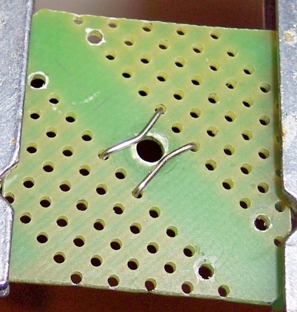
Figure 12 Picture Showing Grounding Wires.
Cut two lengths of yellow wire and two of red wire approximately 2-1/2 inches long. Strip insulation from each end of each wire until there is 11/16 inch of insulation left on the wire.
Use your needle nose plyers to bend the bear ends of one of the yellow wires towards you at right angles to the insulated portion. Look at the board layout and while still holding the wire with the bear ends pointing toward you form the insulated part of the wire into the shape to match the wire connecting between holes D5 and C11.
Flip the board over and insert the end of the yellow wire with the longest part that is bent at 45 degrees into hole C11 from the foil side. Insert the other end into hole D5. The straight part of the wire should run parallel to the gap in the center of the board. The detour that the wire makes should bring it closer to the center than the holes it is passing through. Remember you are working from the opposite side of the board than the drawing view.
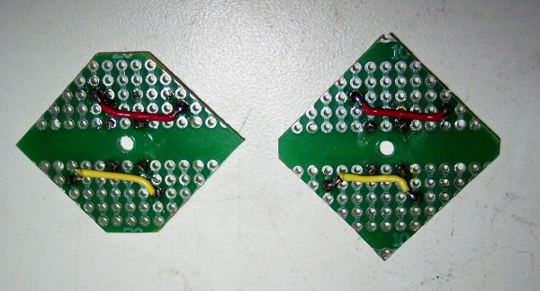
Figure 13 Picture Showing Wiring on Foil Side of Board.
Bend the ends of the wire on the component side over to hold the wire in place. Turn the board over and solder the wires to the foils.
On the component side straighten up the wires and cut them off with a flush cut cutter. If you don't have one of those cut them as close as you can and then use a small file to file the ends down flush with the board.
In a similar manner prepare and install the other yellow wire on the other board.
Prepare one of the red wires and install it in a similar manner. This wire connects between holes H7 and G13. It is an exact mirror image of the yellow wire.
Prepare the other red wire and install it on the other board.
Use an ohmmeter or some kind of continuity tester to check for shorts between traces.
Locate two transistor IF transformers with yellow slugs and two more with white slugs. Each transformer has 5 round pins that connect to the coils and two flat lugs that are on the edge of the cans. These last two serve to ground the cans to circuit ground. We will ground the cans in a different way. Grasp one of the flat lugs in your needle nose plyers and bend it back and forth until it breaks off. These lugs have been designed to break in this way. If part of the lug doesn't break off grasp what is left and try to break it off. If a little rough edge remains behind remove it with a small file.
Break off both lugs on all four transformers.
Install one of the yellow transformers in holes H5, I6, J7, F7, and H9. Solder the lugs to the foils but do not cut off excess lug length. The yellow transformer goes on the side with the red wire.
In a similar manner install the other yellow transformer on the other board.
Install a white transformer in holes C9, A11, E11, B12, and C13. Solder the lugs to the foil but do not cut off excess lug length.
In a similar manner install the other white transformer on the other board.
Strip about 2 inches of insulation from any color wire do not cut it off the roll. Pass the bear end through hole J8. Lay the bear wire against the transformer and position the end just below the indentation in the transformer can. Wrap the wire around the board or do whatever you must to make it stay where you want it. Position the board on edge and solder the wire to the transformer can. Cut the wire on the foil side of the board leaving about half an inch. Solder the wire to the foil and cut off the excess length.
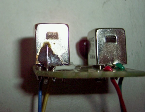
Figure 14 Picture Showing Can Grounding Wire Soldered to Can.
In a similar manner install another wire at hole A10.
Repeat these steps for the other board.
Cut about 2-1/2 inches of white wire. Remove insulation from each end so 7/8 inch of insulation remains. Connect this wire from hole J9 to hole E7. Route this wire around the yellow transformer as shown. On the side next to the center hole push it right up against the transformer. Solder both ends and cut off excess lead length.
Do the same for the other board.
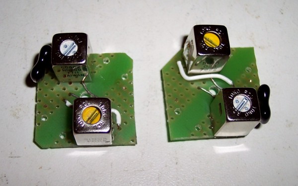
Figure 15 Picture Showing Position of White Wire.
Cut two 6 inch lengths of the following wire colors. Red, yellow, green, and blue. For 8 wires in all. Strip 1/2 inch of insulation from each end of each wire.
Form one end of each wire into a U shape as shown in the picture below.
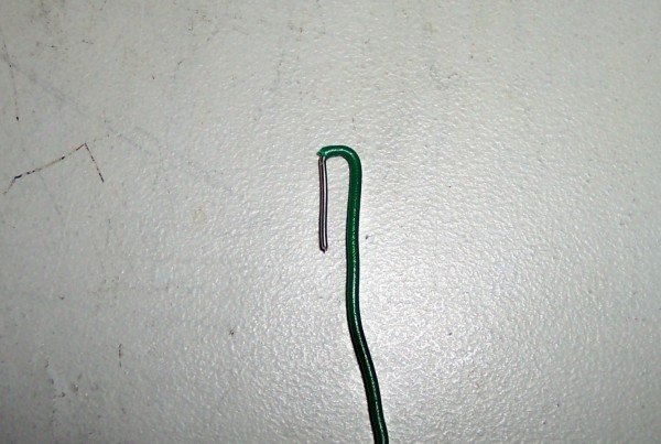
Figure 16 Picture Showing Bending of Connecting Wires.
Pass the straight end of one of the blue wires through hole F4 from the component side. Pull the wire all the way through and pass the bear end into hole F5. Pull the wire down firmly against the board, solder the wire at hole F5, and cut off excess bear wire.
Pass the straight end of one of the yellow wires through hole E4 from the component side As you did before insert the bear end through hole E5, solder, and cut.
In exactly the same way install a red wire into holes F14 and F13.
Install a green wire into holes E14 and E13.
In a similar way install the remaining 4 wires into the other board.
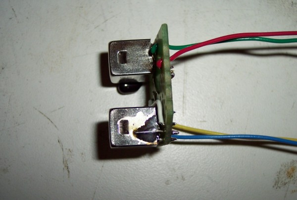
Figure 17 Picture Showing Completed Board with wires attached.
Match up one of the circuit boards and one of the spacer boards. Line up the two according to your marks and feed the wires through the holes in the spacer board. Feed the wires through carefully so as not to put too much force on the connections to the PC board. Before the screw in the spacer is ready to pass through the hole in the PC board, drop an insulating washer over the screw.
Gently push the PC board down on the screw. You will meet with some resistance because of the grounding wires. Don't force things, take your time.
When the PC board is all the way down on the screw, thread a nut onto the screw and tighten it down using your modified nut driver.
In a similar manner match up and assemble the other PC board and spacer.
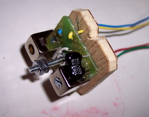
Figure 18 Picture Showing PC Board and Spacer Assembly.
The picture shows the two jam nuts already installed. Instructions for doing this will be given following the resistance tests.
Resistance Tests.
Fire up your ohmmeter be it digital or analog. Clip one meter lead to the screw holding the PC and spacer boards together.Touch the other meter lead to each wire in turn. The meter should show infinity on the highest range.
Touch the meter lead to the shells of each transistor IF transformer. The meter should indicate less than an ohm on the lowest range.
Unclip the meter lead from the screw and clip it to both the green and yellow wires at the same time. Clip the other meter lead to the red and blue wires at the same time. The meter should read infinity on the highest range.
Set your meter to the lowest range and connect one meter lead to the blue wire and the other ohmmeter lead to the red wire. The meter should indicate in the range of 8 to 9 ohms.
Connect the ohmmeter to the green and yellow leads. It should indicate in the range of 5.8 to 6.5 ohms.
If you get readings that are just a couple of tenths of an ohm outside these limits I wouldn't worry. If you are way off like 1 ohm or 25 ohms, worry.
There isn't much that can go wrong with this project because it has so few parts.
Final assembly.
Now look to the IF transformer can or cans you removed from the old radio. It is assumed that you have removed and either saved or thrown away the guts of the cans.Look inside the cans. Most likely there will be some insulating material around the inside top of the cans. This is unnecessary so unless it is peeling away there is no need to remove it. However, there may be an insulating washer glued to the inside top at the center hole where the mounting screw goes through. This must be removed so the mounting screw can make electrical contact with the can to ground the shields of the transistor IF transformers.
WARNING!
In the following step the empty IF can will be heated by your soldering iron. It will be too hot to hold in your bear hand. Use a glove.Insert your soldering iron tip into the hole that is in the center of the top of the can. Push it in all the way until it makes contact all the way around. Do not use force.
Hold the iron upright with the can on it for a couple of minutes.
Hold the can in your gloved hand and remove it from the soldering iron. Use a sharp object such as a scribing tool or a small screwdriver to scrape around the hole on the inside of the can. Let the can cool thoroughly before proceeding to the next step.
Start a nut on the screw and run it down until the top of the nut is even with the tops of the transistor IF transformers.
Start a second nut on the screw and run it down until it runs into the first nut as shown in the picture above.
Hold the assembly in some kind of vice or have someone else hold it for you. Hold the lower nut in your needle nose pliers while tightening the upper nut with a nut driver. This is called a jam nut and will keep either nut from rotating.
Straighten out the wires and using them as a handle push the assembly into an old IF can. Pass the end of the screw through the hole in the center. Thread another nut onto the screw to hold things together while you inspect it.
The alignment slugs of the transistor Ifs won't align with the holes in the old IF can. The holes will have to be moved by filing.
Most likely you will be able to see the tuning slugs at an angle through the holes. Use a pencil to mark where the slugs are relative to the existing holes.
Figure 19 Picture Showing Fully Assembled Replacement IF Transformer.
Remove the assembly from the can and file the hole with a round file until the slugs can be accessed through the holes.
OK, so I overdid it a little. So sue me.
Repeat the resistance tests. If it passes you more than likely have a working IF transformer.
Alignment.
Alignment of any IF amplifier is critical to the operation of the radio or receiver. This is not meant to be a general alignment procedure. Some radios, particularly older ones employed stagger tuning of the IF transformers and a simple peaking will often result in an oscillating amplifier. The method of feeding signal is the only part of this procedure which may be applied to any type of receiver.Set your signal generator or function generator to 455.0 kHz and the amplitude to 1 volt RMS.
Use a BNC to alligator clips cable to connect the generator's output to ground and grid 1 of the converter tube. Note, if the radio has a line connected chassis be sure to use an isolation transformer. The low output impedance of the generator will stop the local oscillator and permit injection of signal into the IF amplifier without any abnormal loading of the tuned circuits.
Connect a high resistance DC voltmeter, preferably analog, or an oscilloscope set to the DC position, to the AGC line of the radio.
You should have a negative reading of 1 volt or likely more. Lower the output of the generator until you are reading approximately 1 volt on the meter or scope.
Adjust all 4 tuning slugs for a maximum reading.
Again lower the output of the generator until you read about 1 volt. Carefully adjust all 4 slugs for maximum. Go through the adjustments several times as there is some interaction between the adjustments.
Disconnect the signal generator and voltmeter and enjoy listening to your newly repaired radio.