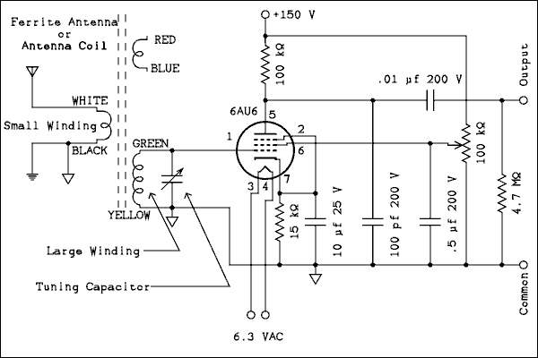
For a verbal description click here.
In these modern times it's not easy to find parts. Some of you may be afraid of winding coils (it took me many years to get over helixaphobia. However my investigations have led me to the inescapable conclusion that winding coils is the best way.It's really not that hard and it is guaranteed to be painless. I have devised a method in which you use Double Stick (stickem on both sides) Scotch Tape to hold the wire in place while you wind the coil. One of the most frustrating things about winding a coil is what happens when you let go of it. The double stick tape prevents this from happening. To learn how to wind your own coils click here.That's what I thought three years ago. I have found that some of the old coil sets are still available. The P-C70-A from Antique Electronics Supply works just as well and maybe a little better than the coils you can wind. Winding coils is an interesting experiment and you may want to do it just for the fun of it. If you would rather skip all the fun you can. Some additional instructions have been added below.
If you don't have a variable capacitor you will need to buy one. If you would rather not wind your own coils there are ferrite antennas and antenna coils for sail. Click here to learn what to buy and where to buy it.
Another source is to take a transistor radio apart to salvage the tuning capacitor and ferrite antenna. It's kind of fun tearing up one of those disgusting little things and you might learn a thing or two in the process. The parts you get are of limited usefulness which is why I really don't recommend it. If you have the time and the inclination give it a try. Just click here.
The plate detector is so named because the rectification takes place in the plate circuit, as opposed to the grid circuit. The tube is biased very close to cut-off. As the grid of a vacuum tube is made more negative the plate current gets smaller and smaller. Finally, a point is reached where the plate current is zero. Ideally, this would be a straight line and if the grid is biased to exactly the point where the plate current is zero the tube becomes a rectifier. See How a Vacuum Tube Works. Of course nothing is ever ideal but the graph is close enough to a straight line to make it work. If an AC, or RF, signal is applied to the grid the negative excursions have no effect because the plate current is already zero and it can't go any lower than that. The positive excursions produce pulses of plate current. Thus, the wave form of the plate current is the half wave rectified version of the input signal. If that signal is an amplitude modulated radio wave the plate current will be a reproduction of the original modulating audio signal.
Here is the diagram.

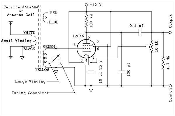
For a verbal description click here.
I have had inquiries about how these one tube radio circuits work with 12 volt car radio tubes. I can say that this one works quite well thank you. It's not quite a plug and play but a few component value changes will have you listening to local stations with no danger of being shocked. The audio output from this circuit is quite low and you will need a fairly sensitive amplifier to listen to it. Headphones are out of the question.

For a verbal description click here.
If you are using the Hammond antenna coil from AES connect it as follows. Pins 2 and 4 to ground. Pin 1 to the tuning capacitor and grid of the tube. Pin 3 to the antenna. This runs counter to the connections recommended by the manufacturer but I know what I am doing. Try connecting a 33 pf capacitor between pins 1 and 3. Refer to the Crystal Set article. See how the performance changes with and without the capacitor.
You can also use this circuit with modern stereo headphones by connecting the primary of a 10 k ohm to 2 k ohm audio transformer in parallel with the 4.7 meg ohm resistor. Also see the Crystal Set article referred to above.
The relatively large value of the cathode resistor serves to set the tube near cut-off. The cathode current (plate current plus screen current) is highly dependant on the setting of screen voltage but with the screen set at about half of B+ the current is about 170 microamps. There is a slight increase when a strong local station (the only kind you can get) is tuned in.
You will notice right away that the tuning is sharper than with the grid leak detector. That detector takes power from the tuned circuit which goes into charging the capacitor and is then turned into heat by the resistor. Taking power from the tuned circuit lowers its Q thus widening its bandwidth. (Don't bother trying to feel the heating of the resistor. The amount of power is so small that you can't feel or even measure the temperature rise of the resistor.) In this circuit the grid is always negative with respect to the cathode and so does not draw any current at any time. By not taking any power from the tuned circuit it has the maximum Q it can possibly have. If you have several local stations close together in frequency you will find it possible to listen to just one without a babble of voices in the background.
If you would actually like to BUILD a one tube radio in some sort of permanent form this is one I would recommend. Have fun, more to come.
Home This page last updated June 23, 2011.