For a verbal description click here.
For a verbal description click here.
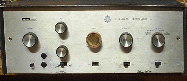
I purchased this unit on eBay knowing it didn't work. But I had wanted an A-300 ever since I was in college. When I moved off campus my roommate had one. We teamed it up with my Stromberg-Carlson AM FM tuner and we had a first class radio. My Stromberg-Carlson still works and when I saw this A-300 on eBay I just had to have it. Ones that work go for some big bucks so I was glad to get this one for a bargain price. A missing knob accounts for the odd man out knob.
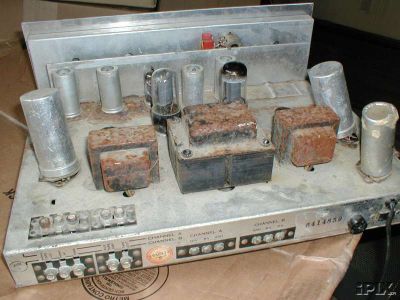
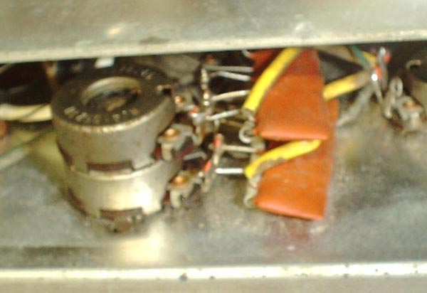
I knew from the pictures on eBay that it was pretty much a basket case so I was not surprised when it arrived. As you can see there was a lot of rust and the phonolic mounting plates on the filter capacitors were all broken. More than half of the tubes were missing. I made a layout diagram of tube placement and then turned my attention to the capacitors.I made careful drawings of what components and colored wires went to the lugs of the capacitors. These weren't what you would call draftsman quality but they had to be accurate. Then I started unsoldering the wires from the lugs and testing each section of each capacitor. As I progressed through this procedure and found each cap to be good I kept saying to myself "Why did they throw this thing away?" As I finished testing each cap I drilled out the rivets and replaced the phonolic mounting plates with new ones. Where did I get them? I had them on hand. In the old days when ever you bought a can type cap there was a metal and a phonolic plate in the box. If the cap was a replacement there was no immediate use for these plates so I just kept them. I never throw anything away.
With all tubes removed I tested the power supply and all seemed well. I was just about to tube it up and give it a listening test when I decided it would be a good idea to test the output transformers even though the odds of a failure are small. Oops? Why do I have the feeling you are ahead of me. One of them had an open on one side of the primary.
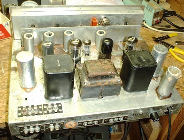
All right. Let's get the old tube stereo down from the attic. That's the same home brew one you can see elsewhere on this site. It used two pairs of 6V6s so the output transformers should work. They are high quality, potted, fully shielded transformers. The original ones in the H K had secondary taps for 8 and 16 ohms. These have taps for 4, 8, and 16 ohms. There weren't enough screws on the back to use all three taps. Since I have a couple of 4 ohm speakers and no 16 ohm ones I decided to hook up the 4 and 8 ohm taps and use the 16 ohm tap just for feedback.
New holes drilled in the chassis, transformers mounted and wires soldered, time for a listening test. Sounds good so I installed it in my main stereo system.
It didn't take long before the sound started cutting off and on. Leaving it in place I connected up a signal tracer and waited for the condition to recur. I didn't have to wait very long. I moved the tracer forward until the signal it was getting cut out at the same time as the main speakers. It turned out to be a coupling capacitor. The caps were those waxed paper type that look so ugly in old radios. You and I both would have thought that H K would have used higher quality caps but apparently they didn't. Because both channels were acting up I concluded that several of them were bad. I ordered some brand new poly plastic caps, yes you can still get them, and replaced every one in the amp. In the process I think I discovered what took out the output transformer. One of the coupling caps to one of the 6V6s was totally open. If only one output tube is getting drive it could put an extra strain on that side of the transformer. You could argue that it's not an A-300 anymore because it doesn't have the original output transformers. Granted.Some kind person has given me a set of HK transformers. Thank you. As for the odd one, someone contacted me who needed one and offered to buy it. I traded it to him for some tubes. The one leftover OT is gone so it won't do you any good to contact me offering to buy it.
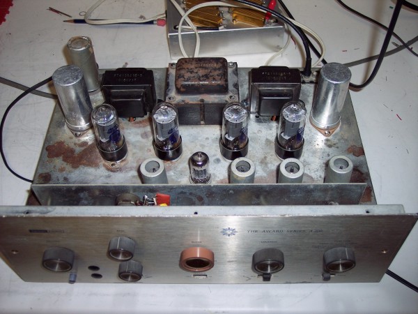
Here is how it looks with the proper output transformers installed. I don't have the patients to remove bits of rust with a Q-tip. The rust will just have to stay. Maybe after I am gone the amplifier will come into the hands of a more ambitious restorer and the rust will be removed.
The schematic Diagram.
When I was living with my roommate's A-300 I decided I was going to rip off -- er -- borrow -- er -- recycle some of the circuitry. I copied parts of the schematic in an engineering notebook. Why I didn't take the manual down to the copy machine and copy the whole thing I don't know. Unfortunately we can't change the past. I have parts of the schematic but not the whole thing. Fortunately it is easy to trace out tube circuits except where those little modules were used.
Most service men I knew called them printed circuits. In today's terminology they are thick film monolithic circuits. These were the for-runners of modern ICs. They contained resistors and capacitors and it was just a short jump to include transistors. Manufacturers such as Harman-Kardon could and did have these made to their specifications. If you have something with one of these circuits which is defective, and no schematic you are up a polluted waterway without sufficient means of locomotion. Fortunately I copied the tone control so I have the schematic diagram. The loudness control and rumble filter also used these PCs but I didn't copy them. Below is as much of the schematic diagram as I could trace or had copied.
WARNING! THERE ARE ERRORS AND OMISSIONS IN THIS SCHEMATIC DIAGRAM. SEE THE OFFICIAL SCHEMATIC BELOW FOR THE CORRECT CIRCUITRY.A very interesting point is the phase splitter and the tube just before it. The cathode of the half of a 12AX7 goes to the same voltage divider as the cathode of half of the 12AU7. If you connect the cathodes of two triodes together and couple the plate of the first to the grid of the second you have a schmitt trigger. The cathode is tapped way down so the result is positive feedback but not with enough loop gain to sustain oscillation. I breadboarded this much of the circuit and made some measurements. The gain measured out as a whopping 515. At the necessary voltage output to drive the 6V6s the distortion was 0.90% from the cathode of the 12AU7 and 0.92% from the plate.
I decided to see how much of an increase in gain and distortion this positive feedback was producing. First I measured the DC voltage at the cathode of the 12AX7. Then I disconnected the cathode from the junction of the 300 ohm and 20 k ohm resistors and inserted a cathode resistor and bypass capacitor. I used an adjustable resistor and set it for the same DC voltage as measured above. Then I measured the gain and distortion again. The gain was 55.3 and the distortion was 0.38% from the cathode and 0.36% from the plate. Interesting. The gain was increased by 19.4 dB while the distortion was increased by 7.8 dB.
What this does for the overall performance of the amplifier is to increase the amount of feedback by almost 20 dB without adding a lot of open loop distortion. The open loop distortion of 6V6s is probably about 3%. There is no tube manual data that matches the operating conditions used in the A-300.
In a string of amplifiers the total distortion is given by the square root of the sum of the squares. With 3% in the outputs a change from 0.91% to 0.37% in the driver would not be all that significant. The numbers are 3.13% to 3.02%. An overall increase of 20 dB in feedback would give a total of approximately 30 dB. I am basing this on the little newcomb amplifier which has about 10 dB of feedback. So if the H K has 30 dB of feedback the closed loop distortion will be about 0.1%. I guess that's why the front panel of the amplifier bears the legend "Award winning A-300".
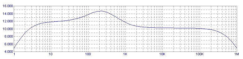
Here's the reason this little amplifier sounds so good. I knew from my work on the Dedicated Headphone Amplifier that the tone control had a small peak in its frequency response. I simulated the 12AX7 driving stage and the tone control and here is what I got.n
For a verbal description click here.
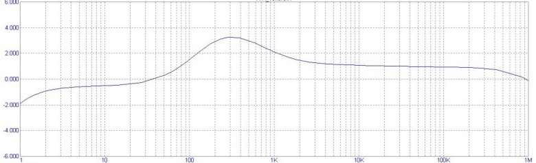
The feedback loop alters the frequency response of the tone section shown above. Here is the corrected graph.
The vertical axis is in dB. Remember there is an amplifier tube here which more than makes up for the 20 dB loss in the tone control. The horizontal axis is logarithmic in frequency. Both Bass and Treble controls were set to the center of rotation, 10% because these are audio taper pots. The first thing you are likely to notice is that peak just a shade above 200 cycles. In my experience with graphic equalizers I have found that this is the presents band. The ear is extremely sensitive in this frequency band and can pick up a very small change in the amplitude. The slightly more than 4 dB boost from mid and high frequencies accounts for the warm sound of this amplifier.Then you will notice that the amplitude at 20 cycles is up almost 2 dB from that at 20,000 cycles. This gives the amplifier a subtle but definite bass boost with the tone controls set to what is supposed to be flat.
I tried in vain to get rid of the bass boost and the peak by juggling values both on the breadboard and in the simulation. No doubt the HK engineers did the same thing. I imagine that when they put the design up for listening the top brass of the company fell in love with the warm sound it produced. If people like it so much why try to change it.
I can't tell you what award it won but I assume that the judges also loved the sound produced by this slight bass boost and the presents peak without even realizing what they were hearing.
The amplifier does have a good sound. I listen to it every day. I'm not one of those people who listens at a window rattling, floor trembling level so I don't run it into clipping.
Update, August 27, 2013.
To refresh your memory, earlier on this page I wrote. "You could argue that it's not an A-300 anymore because it doesn't have the original output transformers. Granted. Some kind person has given me a set of HK transformers. Thank you. As for the odd one, someone contacted me who needed one and offered to buy it. I traded it to him for some tubes. The one leftover OT is gone so it won't do you any good to contact me offering to buy it."Now, when did all this happen. It appears that I bought the amp from eBay in early September 2003. I wrote it up for this site in March of 2004. Somewhere in between these dates is when I made the repairs and installed the non original output transformers. The original H-K transformers were given to me in November 2009. These dates aren't 100% certain. They are based on file dates and some creative reconstruction of memories.
It has taken me all this time to get around to installing the transformers. Well, I was building a woodshop and doing a major remodel of my electronics lab. In April of this year I acquired an official Harman-Kardon schematic and here it is.
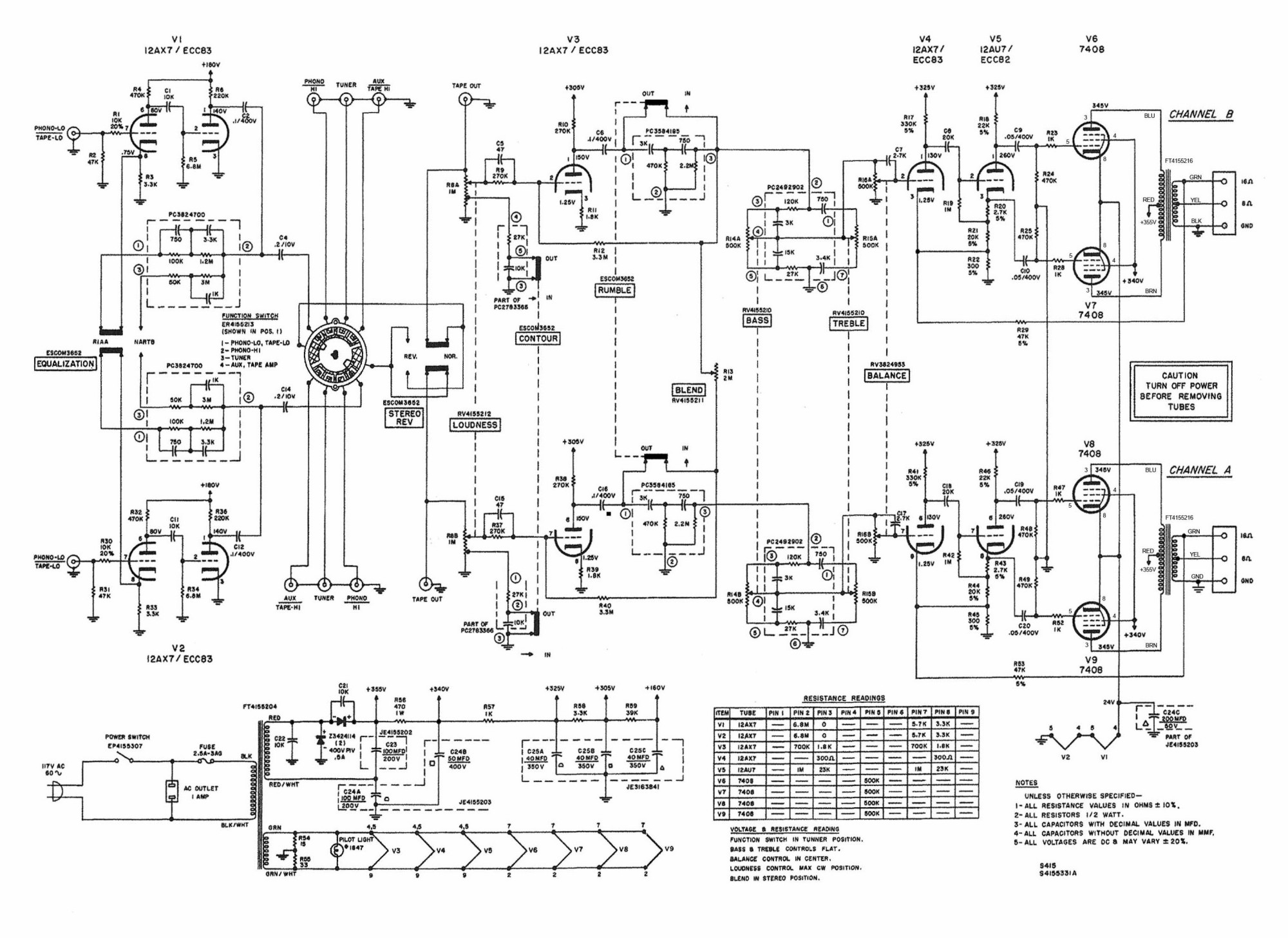
I apologize for making the schematic so large in comparison to the rest of the page but any smaller and the smallest text becomes so pixilated as to be unreadable. As it is it is barely readable to me so I assume that you can read it. The original is twice as big as the one shown here. Maybe someday I will redraw it in MaxCAD to be more compact but don't hold your breath. You see how long it took me to install the output transformers.Another concession to current circumstances is the replacement of the 7408 output tubes with 6V6GTs. 7408s are out of stock with every tube seller that I know. So, a brand new matched quad of Electro-Harmonix 6V6GTs are in the amplifier.
A note on my schematic as opposed to the official one. Mine was traced out and I seem to have missed the negative feedback loop around each of the V3 triodes. In the official one there is a missing tie dot where the movable contact of the rumble filter switch connects to the output of the rumble filter. Follow the connection from pin 7 of V3 through the 3.3 Megohm resistor. Where it appears to cross the line from the output of the filter there should be a dot indicating a connection.
I ran a new simulation of the tone circuit with the NFB included and placed it just below the original one for easy comparison. The beneficial effects of NFB are clearly shown.
Output power just before clipping, 12.5 watts both channels driven.
Frequency response -3 dB from level at 1,000 Hz.
Less than 20 Hz to 44,000 Hz.Distortion at various power levels at a frequency of 1,000 Hz.
Power (W) THD (%) L THD (%) R 12 0.72 0.76 6 0.41 0.415 3 0.52 0.465 1 0.287 0.285 Why is the distortion higher at 3 watts than at 6 and then lower again at 1 watt. I don't know but I would like to know exactly what it does between points. So I'm going to run the experiment again with more closely spaced points. It's been two days since I collected the data above and one thing I have learned is it is not good to mix data from different days. So I'll run the whole thing again. Let's see what happens.
Power (W) THD (%) L THD (%) R 12 0.73 0.80 11 0.62 0.66 10 0.54 0.50 9 0.515 0.40 8 0.505 0.36 7 0.495 0.355 6 0.47 0.39 5.5 0.45 0.40 5 0.502 0.42 4.5 0.53 0.45 4 0.535 0.48 3.5 0.56 0.51 3.25 0.56 0.502 3.0 0.55 0.485 2.75 0.54 0.49 2.5 0.51 0.46 2.25 0.48 0.43 2.00 0.455 0.4 1.75 0.395 0.385 1.50 0.35 0.36 1.25 0.32 0.32 1.00 0.307 0.295 0.75 0.25 0.255 0.50 0.193 0.22 0.25 0.165 0.188 Well that's interesting, but I still don't know what's causing it. Of course we all know that tubes have their nonlinearities. One tube is not being operated in isolation. It's not hard to imagine how the combination of tube characteristics could be a little less linear at a lower signal amplitude than it was at a higher amplitude.
Distortion at various frequencies at 1 watt output.
20 7.8 3.9 30 5.7 2.6 40 4.3 2.25 50 3.3 2.0 100 2.1 1.25 200 1.02 0.67 500 0.41 0.50 1,000 0.37 0.49 2,000 0.36 0.48 5,000 0.415 0.495 7,500 0.46 0.51 10,000 0.58 0.54 15,000 0.52 0.55 20,000 0.55 0.57 Now I need to go back and run the contest winning amplifier at 1 watt to see how they compare.
IMD
* Next night.
Power (W) IMD (%) (L) IMD (%) (R) * IMD (%) (L) * IMD (%) (R) 6 0.76 1.15 0.78 1.40 3 1.62 1.92 1.40 1.90 1 1.35 4.1 1.09 1.2 I have a Heathkit IM 5248 IM distortion analyzer on the way. It turned up on eBay, I bid on it and won it. I don't know if someone saw my comments on the "Contest Winning Amplifier" page or it was just coincidence. Either way I will be able to verify the calibration of my home brew analyzer. It will be interesting to see how they compare.
That seems to be about all there is to say. May you have good luck in your restoration projects.
Home
Thank you for visiting my page at Angelfire.
Please come back and visit again!This site begun March 14, 2001
This page last updated November 16, 2009.