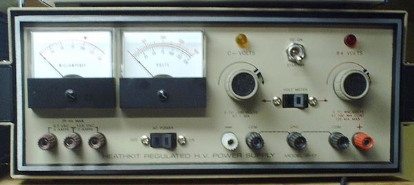
I purchased this unit on eBay without knowing if it worked or not. But with something this old you should expect the worst. That way you won't be disappointed. At the initial trial it seemed to be working but the voltage was not zero at the counter clockwise end of the control as it is supposed to be. I opened it up to set the zero voltage and maximum voltage adjustments but they were already set to their extremes and would not come into adjustment. I could have lived with it as the previous owner had but I like things to be right.Fortunately the manual had come with it so I opened it up. The schematic diagram had some pencil markings on it indicating that someone had gone through the tests I was about to perform. Here is a simplified diagram of the circuit so you can see what I'm talking about.
For a verbal description click here.
I unsoldered the pots and resistors in the voltage divider which connects to the grid of the 6BH6. They all tested within tolerance. I also checked the plate and screen grid resistors that go to the 6BH6. All were good. It was then I noticed that the front panel was caved in. No doubt kicked in by the very frustrated previous owner.I told myself "I can't let this thing beat me." After some very careful observation I found that the grid of the 6BH6 was about 25 volts negative with respect to the cathode. The voltage listed in the schematic indicated this voltage was suppose to be about -2 volts.
I popped the tube out of its socket and into the tube tester. It was good. Hmmm? All the voltages around the tube were what they were supposed to be. So what's wrong? I decided to play a long shot because I didn't have any short ones left. I found another 6BH6 in my stock of used tubes and it tested good. I plugged it into the power supply and ---- it worked right. The voltage from cathode to grid was -2.4 volts and things would and did come into proper adjustment.
I removed everything from the front panel, yes everything. That wasn't such a big deal as you might think for a long time Heathkit builder such as myself. Straightening it out was not as hard as I thought it might be. Then after putting it all back together I had a real nice and fairly compact tube power supply.
But what's with that tube? I set up a test circuit as shown here.
For a verbal description click here.
I plotted plate current versus grid voltage with plate and screen voltages held constant. In fact I used the very power supply this article is about. Then I plotted a known good 6BH6 and for comparison a 6BA6 which is a remote cutoff pentode. The results are shown below.
For a verbal description click here.
Just to see what would happen I set my tube tester up to test a 6BH6 and plugged a 6BA6 into it. The meter indicated good. So what's going on? I'm not quite sure except that the 6BH6 that apparently was supplied by Heath was not a sharp cutoff tube as it was supposed to be. Since its curve falls between the sharp cutoff and remote cutoff it would appear to be a semi remote cutoff tube. Email correspondence have suggested that it might have been a 6BZ6. I have been too busy, or maybe too lazy, to run the characteristic on a 6BZ6 to see how close it comes. My email has informed me that mislabeling tubes at the factory is rare but not unheard of. The internal appearance of a 6BZ6 is quite different from a 6BA6. The original tube in the power supply looked like a 6BA6.CONCLUSIONS.
1) The 6BH6 was messed up some how at the tube factory. This is a very low probability occurrence but it did happen.
2) Tube testers can lie so don't stake your life on them.
3) When in doubt change the tube.
Home
Thank you for visiting my page at Angelfire.
Please come back and visit again!This site begun March 14, 2001
This page last updated March 17, 2004.