For a verbal description click here.
I have begun to have doubts about the results presented in this article. Now that I have built a flexible test bed for power amplifiers and purchased an assortment of output transformers I intend to do this work over again. I will leave the old work up but watch this space for an update. This message will disappear and the "last updated" date at the bottom of this page will change.It is a legend among audiophiles that power triodes give better sound than pentodes. OK, so why aren't there any? There hasn't been a good power triode since the 2A3 which hasn't been manufactured since the 1930s.
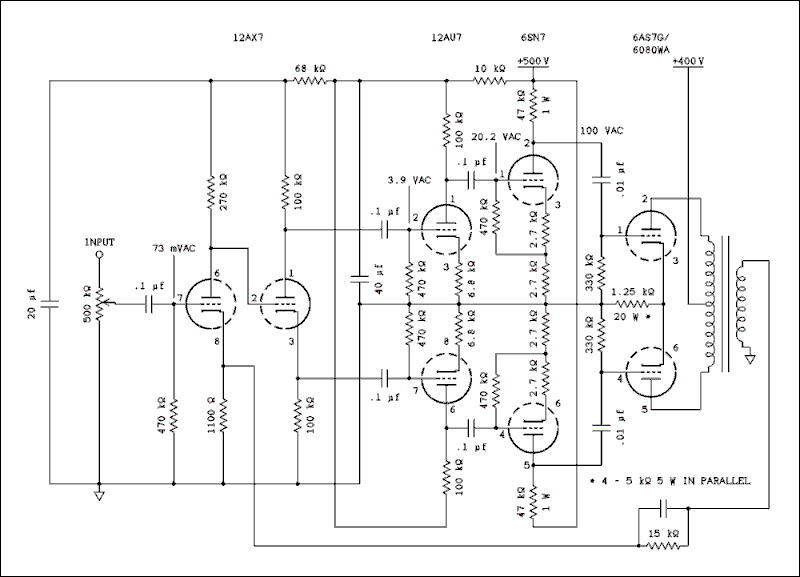
I am told that 2A3s are in fact still being manufactured today. Well, live and learn. Maybe if I live long enough I'll learn not to make flat statements like that.The only tube I know of that was still being made at the end of the tube era is the 6AS7G which was never intended to be an audio tube. It can be found in Tektronics oscilloscopes, Hewlett-Packard signal generators, and Lambda power supplies. It is used in these units as a regulator pass tube. It is a duo triode with a combined plate dissipation of 26 watts. To find any bigger triodes you have to go up to transmitting bottles that are capable of a kilowatt or more and need 2000 volts on the plates.I thought maybe I could parallel up enough 6AS7Gs to get a respectable power level, say 50 watts. But before I did that I wanted to know how it would perform as an audio power output tube. There is a circuit in a 1950 RCA tube manual showing one of these tubes being used in an amplifier. There was no negative feedback and no distortion figure given. I made some modifications to the circuit and here is my version.

For a verbal description click here.
The 6SN7 driver circuit is lifted right from the RCA tube manual. I used a different phase inverter and a 12AU7 stage between the inverter and the driver. I needed 100 volts RMS at each driver plate and I wanted a distortion less than 1 percent. I got .6 percent. If you need a lot of drive at low distortion there's a circuit for you. The feedback shown was not connected.
The circuit was built on a recycled chassis using components soldered to terminal strips, but not wrapped around, as described on other pages of this site. The results were more than a little disappointing. I could get 12.5 watts out of it but at 6.5 percent distortion. Even when the power was lowered to 5 watts the distortion was still 4 percent. When I connected the feedback I couldn't get the distortion below 1 percent. Oh, well, these tubes were not designed for audio service.
Someone did manage to get respectable performance in single ended operation. To read the article click here.
Triode connected pentodes.
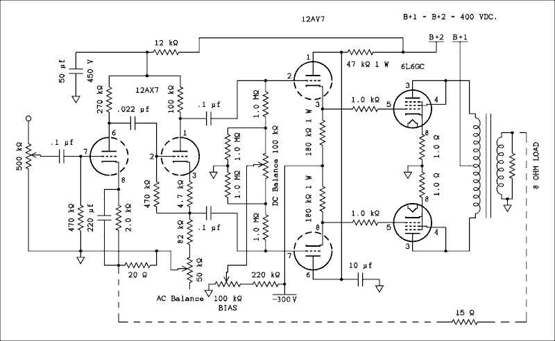
If you tie the screen grid of a pentode to the plate you supposedly have a triode. That seems kind of like cheating, afterall there is another grid in between the screen grid and plate. My tube manual doesn't even have data for two 6L6s in push-pull triode connected. Anyway you have to lower the plate supply voltage so as not to exceed the maximum screen grid voltage.Well, considering the poor performance of 6AS7s I decided to try a pair of triode connected 6L6s. Here is the circuit.

For a verbal description click here.
As I ran tests on this amplifier using triode, ultra linear, and conventional pentode connection, I got inconsistent results. I soon realized it depended on which 6L6GC was in which socket. I dropped a couple of matched 1 ohm resistors into the cathodes and found I had a rather serious unbalance for both AC and DC. The balance controls were added to the circuit. Would balancing the 6AS7Gs have made a difference? Probably so but that investigation will have to wait until I get through evaluating 6L6s in various configurations.The starting plate supply voltage was set to 270 volts. The control grid bias was optimized for minimum distortion at 5 watts. The voltage was -28 volts. With no global feedback clipping set in at 5.8 watts. At 5 watts the distortion was 3 % and at 1 watt it was 1.6 %.
With 20 dB of global feedback the distortion figures were, 5 watts, 0.76 % and 1 watt 0.26 %.
Not too bad but kind of low on power. Using 6L6s or 6L6GBs the voltage couldn't be any higher than 270 volts because that is listed as the maximum screen voltage for these tubes. Strictly speaking the peak screen voltage was about twice that but data on other tubes and for a single ended triode connected 6L6 seemed to use the max screen voltage as the operating voltage for a triode connection.
Then I substituted a pair of 6L6GCs which have a maximum screen grid voltage of 400 volts. A boost in plate voltage would require a higher load resistance. I increased the load to 10.9 ohms which gave a plate to plate load of 6800 ohms. Upon testing with various loads this one proved to be the one that yielded the highest power output. (Note: I am using a Hammond 1645 which I have wired for 8 ohm output and has a plate to plate load of 5000 ohms.)
I found with 400 volts on the plates I could get 10 watts at 2.3 % distortion. At 5 watts distortion was 1.9% and at 1 watt it was 0.53%. That's quite a bit better than the 6AS7G both in power and distortion but still falls far short of the 50 watts I want.
So What Now?
The audio industry used pentodes for years and all of the surviving hi-fi amplifiers use pentodes from 6V6s to 6550s. The main reason was economics. It's all about money, honey. The tube companies made tubes that the OEMs (original equipment manufacturers) wanted. Pentodes take less voltage to drive than triodes and this meant fewer tubes in the amplifier and less cost to make. Power triodes may or may not have sounded better. We really have no way of knowing because there are no power triodes to use in an amplifier. That is, unless you want to go up to a pair of 811As with 1200 volts on the plates or even 810s with 2000 volts and 500 watts of audio power.As for me I have been advised by a friend to use tubes that I have a lot of on hand. I compared the tube manual data on 4 - 6L6s in push-pull parallel (multiplying the current by 2 for the 2 tube push-pull data), 2 - 6CA7s, and 2 - 6550s. The comparison came out like this.
4 - 6L6s, 53 watts, 2 percent distortion.
2 6CA7/EL34s, 54 watts, 1.6 percent distortion.
2 6550s, 55 watts, 3 percent distortion.
The 6CA7/EL34s are tempting with that 1.6 % distortion figure but I don't have a one on hand and they are mighty expensive. I have only one 6550. What can I do with one power tube. Anyway it comes in with the worst distortion. So, it looks like a quartet of 6L6s in each channel. I have 25 of them and most of them push the tube tester meter into the green. I'll post it as a construction article when I get it finished.
Next; Designing Amplifiers with Global Feedback.
Everybody's entitled to one dumb thing in life so
Throw away your transistor amplifier and get one with tubes in it.
This page last updated March 20, 2005.