A Breadboard
In the process of building equipment needed to work, or play, with vacuum tubes we have constructed several devices. We have neglected one little thing -- a breadboard. I have one that works nicely thank you but you probably don't. So here is one you can build with currently available parts.
for Vacuum Tube Circuits
One Picture is Worth a Thousand Words.
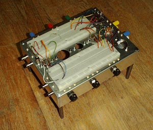
The breadboard shown in the picture is constructed on a 7 x 9 x 2 inch chassis. If you can find one that is 7 x 9 x 3 you won't have to put standoff legs on it as I have on mine. These legs are necessary because the tubes are upside down. A 6V6 would fit into a 3 inch chassis. If you want to play with such tubes as 6L6 or 6AS7G you will need a deeper chassis or longer standoffs.
The breadboarding sockets are standard integrated circuit sockets and are available from Global Specialties and Radio Shack just to name two.
There are two types of holes one for 7 and 9 pin miniature tubes and the other for octal tubes and IF transformers. I have provided a chassis layout in case you want to use it.
Click on image for high resolution version.
The mounting hole spacing is different for 7 pin and 9 pin sockets. That's why there are 4 small holes around the large socket hole. The small holes MUST be drilled first before punching out the larger hole. Your chassis punch likely has a 3/8 inch drive bolt but drill the center hole out to 1/2 inch. Carefully center the chassis punch between the holes before turning the bolt. The large hole will slightly overlap the 7 pin mounting holes. This is not a problem unless you forgot to drill the small holes first.
The Standoff Legs.
The standoffs I used are 4-3/4 inch long. I think I got them from some old equipment I junked out. There were only three so I made the fourth out of 3/8 inch brass dowel rod. You don't need a machine shop to do this. All I have is a drill press adapter for a hand held electric drill and a few hand tools which you can get at any respectable hardware store.
Alternatively you can buy tapped spacers for mounting PC boards. You can use headless screws to fasten two or three of them together to get the length you want.
Potentiometers.
Many circuits you will build need one or more pots. I have included a 500 k ohm audio taper and two 100 k ohm linear taper. Whet I had in mine is a volume control and two tone controls. There's nothing sacred about these values and a special need may require a temporary change. You can install what ever you think is best.
The Connectors.
As you can see I have placed an array of binding posts, Phono jacks and BNC connectors around the chassis. The little gold connector pins are no longer available but that's no real problem. Just drill small holes in the chassis and solder wires to the connectors and bring the wires up through the holes and leave them long enough to reach part of the breadboard. You don't need to use grommets unless you feel like it. On wires that are likely to carry B+ slip a piece of sleeving over the wire to cover it where it comes through the hole.
Preparing the Tube Sockets.
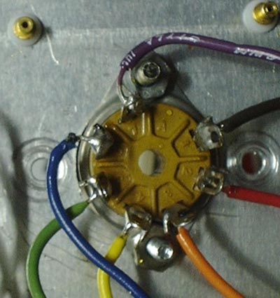
You may want to prepare one or two tube sockets in advance. As you can see from the photo the wires have not been crimped around the pins but simply bent in a hook and soldered. The reason is they are going to brake. You have to use solid wire with this breadboard and after being bent back and forth so many times they ARE GOING TO BREAK. It's just something you live with. Not crimping the wires makes them easy to replace when the time comes.
There is no real need to make what a well known maker of kits used to call "mechanically secure connections". The reason they had builders do that was so if you did a poor job of soldering the connection would hold at least until the warranty ran out.
Intermediate Frequency (IF) Transformers.
IF transformers can also be mounted in this chassis. The kind used with miniature tubes (12BE6, 12BA6, etc.) can be equipped with mounting plates that will fit the same mounting holes as miniature tube sockets. One of these is shown mounted in the photograph. The large IF transformers that go with octal tubes (12SA7, 12SK7, etc) have mounting studs that will fit the holes for octal tube sockets. Somehow I don't think this is an accident.
Well, that's about it. Happy building and happy breadboarding.
This page last updated March 2, 2002