Pictures I have Received.
Over the years that I have been maintaining this site people have sent me pictures of their own projects. As they came in I saved the picture files to drive D and placed the accompanying email in a folder in Outlook Express. Unfortunately I had a major crash in 2004 and lost the emails. The pictures survived because they were on a different drive. Well, I'm going to post the pictures anyway along with anything I can remember. If you recognize your picture and would like to add to or modify the caption please E-mail me. I reserve the right to edit the caption you submit.
This one comes in from Blake. It is based on the Simple Superhet. He gleefully reported to me "IT'S WORKING!" He adds, "The build philosophy is based on projects from "The Boy's First
Book of Radio and Electronics" by Alfred Morgan. I came across this book
after watching a video on YouTube about a fellow who built the one tube
regen that Morgan describes in that book. I built that radio (and in
Morgan's design he suggests using plug-in coil forms which is where I got
the idea) and it works great, but the selectivity is pretty poor. I'm glad
I built that radio because now I have something to compare the superhet's
performance to. Already I can hear much better (excellent, as a matter of
fact) selectivity, although one of our boomers kind of overpowers the
close-by stations." Nice dial Blake.
|

|

|
This gentleman asked me what I would think of making a decorative lamp out of burned out tubes. At least I hope they are burned out.
|
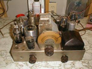
Now here is a truly resourceful do it yourselfer. Not only is he making a radio receiver the way they used to be built, he is making all of his own components. Now that's an accomplishment. Unfortunately I have no memory of his name. See introduction above.
|


|

|
This is quite a system but I don't remember the who or when. See introduction above.
|
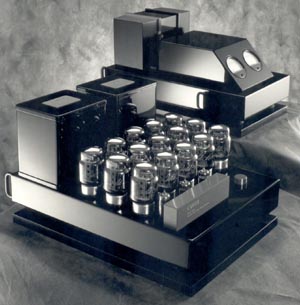
This amplifier belongs to a gentleman named Vic. It uses 15 6550 tubes. Why an odd number? 14 are in push-pull/parallel and the 15th one serves as a voltage regulator on the screen grids of all the others. Vic, I lost your email address again.
|
|

|
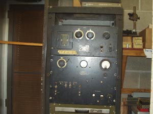
A gentleman came into possession of this equipment and didn't know what it was. There are several more pictures I haven't included. Many of the pieces were made by General Radio but I didn't and don't recognize them. It looks like some kind of test set but that's as far as I can go. I wish I had that Dumont scope.
|
Here we have another intrepid builder. He has constructed his own crystal detector.
|

|


|
The top picture is "1969 One Transistor Solar Powered Receiver from 'The Boys 4th Book of Radio and Electronics' by Alfred Morgan"
The lower picture, "1959 Two Transistor Receiver - a classic CK-722 design. Generic replacements were used in place of the CK-722."
While those certainly are not the dates the radios were built, it is the dates of the books they came from.
Joe Bento, N6DGY
|
This gentleman decided to build his radio in a transparent box.
|

|

|
Here is someone's plug-in coil radio. Obviously there is a lot of work in this project.
|
Here is a surprisingly similar looking radio built by a man named Mark. We have exchanged many emails on the subject.
|

|

|
These are before and after pictures of a restored Atwater-Kent model 80.
|
Pictured is an 80 meter TNT transmitter with a "year" of 1930. The parts include: UX-210 tube, 500 mmfd. Cardwell,
Na-Ald dial, Sangamo condensers, Air-Gap socket, a Bremer-Tully RFC and, of course, Fahnestock clips."
73, Louis VA3AWA
|

|

|
This project is based on the 3 Tube Superhet. Modified to include MW, 90M, 49M, 31M, 25M and 19M. Tuning dial and pointer are from a non-working Lafayette radio. I made the scale with CAD and used plexi-glass for the cover. All in all it's a good receiver and it is very sensitive, especially at night; the SW bands are packed!
Jeremy
|
These pictures come in from Rich Shivers KB3FGJ. He humbly states, "For what it's worth, this does not measure up to the craftsmanship on Dave's
page, but here is my current crystal set." See my links page for a link to Dave's page.
|


|

|
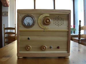
Remember that sometime ago I asked you several questions about the TRF receiver? I remember reading that you wanted to know if anybody is building the radios you describe and, better late than never, I am telling you that long ago I built that radio in permanent form. It is now on duty in the living room, its appearance and performance having been prized by no less authority than (would you believe it ???)…my wife.
The removable top and bottom of the receiver are glass, and so are the forms of the Antenna and Inter-stage coils. The removable front and rear panels and the tuning dial are Ľ" American poplar, and the rest is ľ" red oak except for the homemade knobs that are maple. (I am not equipped to work metal). Yes, yes I know that the military surplus "signal-strength" WW2 Meter was designed to measure radioactivity, but since it is an extremely well built 50-uA f.s. instrument, what's wrong with letting it kick to its heart's content in response to the tiniest tuning changes?…
Giorgio
|
"I am a retired telecommunications engineer who made vacuum tube radios as a boy. I am about to begin construction of a four tube superhet radio. The tube line up from input to output is 6BA7, 6BA6, 6AV6, and 6AQ5. For the IF transformers I plan on using the AES PC-70-RF."
I advised him to place a trimmer capacitor in parallel with the secondary, pins 1 and 2.
"It works! Needed about 600 pf in parallel with pins 1 and 2 for an IF frequency of 455 KHz. Didn't need a damper resistor across pins 3 and 4. Selectivity not great but acceptable."
I asked him about the shields on the coils.
"I went to Target and bought two pressurized cans of body freshener for about $3 each. Each can is 1 1/2" in diameter. I sprayed out the contents, cut each can to a height of 2 1/8 " then spray painted them gray!"
"Doug"
Clever.
|


|
|
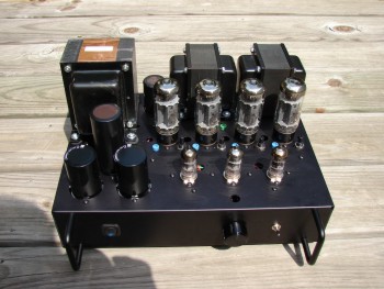
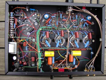
Max - I just finished the Dyna-clone amp. After recognition and
rectification of a few designer errors, it works quite well. The 35 watt
Dyna-clone transformers (from Triode Electronics) seem quite good, but a
little lossy when compared to equivalent Hammond stuff (1650N, 4300 ohm
primary). The HF characteristics are very good though, unlike Edcor, and
the LF seems better than the 1650N. Distortion is very low - about .03
or .04% at 1 watt, about .5% at 45 watts (midband). B+ is about 475 (120
AC in). It uses 6N1P input and 6CA7 output tubes. Damping factor is good (for a tube
amp) at about 12 re the 8 ohm tap.
Tim
|
Send me your pictures and a short description of your project. The text shouldn't take up any more vertical space than the picture. I have my browser text size set to largest. I reserve the right to control my own web page. That means I don't have to put up your pictures if I don't want to.
Home
Thank you for visiting my page at Angelfire.
Please come back and visit again!
This site begun March 14, 2001
This page last updated October 3, 2007.