Deciding how much current you can draw from that unmarked power transformer depends on knowing the resistance of the windings. These values can be as low as 0.1 ohm. Here is a meter to measure them.On these pages you'll find tube circuits you can build but before you start building circuits you need a tube power supply. You'll need 6.3 volts at several amps, usually AC although there may be times when you need DC, and low ripple DC anywhere from 150 to 500 volts at 100 milliamperes or so. Even if you're a most avid experimenter I'll bet you don't have anything like that on your workbench. You could probably supply 6.3 volts DC but that's about it. So let's build one.
Hold on just a minute. If you're a junk collector you may have some old tube power transformers but most of them are not marked. You can find out the voltages by hooking them up to the line and measuring the voltages that come out. BE CAREFUL. These voltages are lethal and even if you survive they are very painful. Knowing the voltages is not enough. Each secondary winding has its own maximum current specification. If even one of these is exceeded by a significant percentage the whole transformer will be rendered useless by a burnout. Knowing the resistance of each winding can help us to estimate the maximum current with enough accuracy to make an otherwise useless transformer useful.
This page is indexed so you can jump directly to what you're interested in. If you already know the theory or would rather not deal with it you can skip to any other part of the article.
Measuring Resistance
The Four Wire System for low resistances
Circuit Description
Construction
Calibration
Operation
Constructing the Special Test Clips
Home
Measuring Resistance
There are two basic methods of measuring resistance. One is to apply a known voltage to the unknown and measure the current. The other is to apply a known current and measure the voltage.Applying a voltage and measuring the current is the method used by almost all analog meters. The equation is
R = V/I
The X = 1/Y equation is very non linear which accounts for the scales which are compressed at one end. If this method were used on a digital meter it would have to contain a microprocessor to make the calculation of resistance based on the current.Applying a current and measuring the voltage is the method used by digital meters and only one model of analog meter I have seen. The equation is
R = V I
This gives a linear scale on an analog meter and requires only placement of the decimal point on either analog or digital meters for proper readings. In the days before transistors the problem was the current source. It's easy with transistors but not practical with tubes.The Four Wire System for low resistances.
When the resistances to be measured are very low, say 0.1 ohms, analog meters are useless because the reading becomes indistinguishable from zero. A four and a half digit DMM may have 1/100 ohm resolution but the resistance of the connecting leads, the contact resistance where the leads plug into the meter and where the leads clip to the unknown is significant compared to the unknown. Not only that but this contact resistance is quite variable so you can't connect the leads together and subtract that reading from the unknown reading. The solution is the four wire measurement system.

For a verbal description click here.
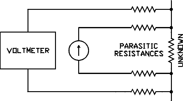
The circuit of a four wire system is shown in the figure. The horizontal resistors represent the parasitic resistances. In the inner loop (the one containing the current source) the current source maintains a constant current regardless of how much resistance is in the loop. (Within practical limits). Because the voltmeter is connected to the unknown through its own leads it measures only the voltage across the unknown. The voltmeter has its own parasitic resistances but because the input resistance of the voltmeter is high these small series resistances have no significant effect on the reading. This measurement method is used when ever the impedance of a circuit is very low. I have devised a way to do it with two clips. The construction of the test leads is given at the end of this article.
Circuit Description
