Nissan KA24E Engine
K&N Air Filter
K&N filters replace original paper filters to increase air flow with excellent filtration. Designed to increase horse power, boost accelleration and improve fuel economy. These filters are washable and reuseable, lasts up to 50,000 miles before servicing and has a 10 year / million mile warrantee. When cleaning, DO NOT over oil the filter! Over oiling will cause the filter to leak and may damage the Mass Air Flow Sensor (MAFS).
K&N's PreCharger and DryCharger filter wraps and the Airforce Pre-Cleaners help extend the service interval when the vehicle is used in very dusty conditions.
Fender Bender International (FBI) Intake
This intake replaces the original air box and filter housing to increase horse power up to 15% and provides better fuel mileage. The only down side to this modification is lost of low end torque.
Use a rubber grommet between the mounting bracket and engine hook to prevent damage to the intake tube caused by engine vibration.
An airflow diverter is included to direct airflow toward the MAFS. Without the diverter, the MAFS will send a false reading and cause the ECU to run in fail-safe mode.


MSD 6A Ignition
The MSD ignition improves power, quickens throttle response, smooths starting and idling, reduces spark plug fouling, improves mileage and reduces emissions. The primary voltage is increased to 470 volts and each multiple spark provides 110 milliJoules of spark energy that lasts last for 20 degrees of crankshaft rotation.
With the MSD ignition installed, the ECU will display code 21 during the self diagnostics procedure. This is normal as the MSD ignition is now controlling the ignition timing.
Installation is very simple. Just cut the positive (black/white) and negative (blue) wires leading to the stock coil and connect the MSD ignition accordingly. Connect the power leads to the battery and you're done.

Vehicles equipped with a stock tachometer (RPM gauge) will require a tach adaptor if it fails to operate. To determine whether you need one or not, connect your tach trigger wire to the tach output terminal on the side of the ignition and if it still fails to operate, the tach adaptor is needed. Part #PN8910
MSD Blaster High Vibration Coil
The windings in this coil are completely encased in a premium epoxy making it impossible for vibration to affect it.
Accell 8.8 Spark Plug Wires
8.8mm oversized wire increases ignition energy due to lower resistance. Spiral wound stainless steel alloy conductor, magnetic suppression, semi-active material, fiberglass/Kevlar core, 500 Ohms per foot resistance.
PaceSetter Headers
PaceSetter headers have thick steel flanges and mandrel-bent mild steel tubing for durability and maximum flow. They provide gains in the low and mid-ranges necessary for off road performance.
The only hang up during installation was the Exhaust Gas Recirculating (EGR) pipe. For easier installation, remove the EGR pipe completely and reinstall it after the header is attached to the engine.
MagnaFlow Muffler
This muffler is encased in an all stainless steel body that reflects heat and resists corrosion better than other steel mufflers. MagnaFlow's straight-through design improves flow to increase horsepower and torque, and you can't go wrong with a lifetime guarantee.
Specifications
Displacement: 145.8 cubic inch (2389 cc)
Spark Plug Type: ZFR5E-11
Spark Plug Gap: 0.041 inch
Ignition Timing / Manual Transmission: 10 degrees before TDC
Compression: 142-192 psi
Fuel Pump: 33 psi w/ vac, 43 psi w/o vac
Idle Speed: 800 rpm
Fluid Capacity (recommended lubricant):
Crankcase including filter: 3.5 qt (API SG 5W-30)
Fuel Tank: 15.9 gal (87 octane)
Cooling System: 9.5 qt (Ethylene Glycol-based Antifreeze)
Engine Control Module (ECM)-ECCS Control Module
The ECM controls the engine. It consists of a microprocessor, diagnostic mode selector, inspection lamps, and signal/power harness. Being able to diagnose your own ECM is a nice feature this unit has. I'm planning on the Jim Wolfe Technology (JWT) computer upgrade in the near future. It has been heavily tested for years and has proven itself with power gains and extreme reliability.
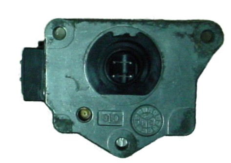
Mass Air Flow Sensor (MAFS)
To prevent damage to the MAF Sensor, remove it before
spraying any type of cleaner into the throttle body.
To clean the sensor, carefully remove it from the throttle body and wipe the tiny wires with a cotton swab and rubbing alcohol. Be careful not to damage the delicate wires as replacement is quite expensive.

If the output voltage of the MAFS is above or below the specified value, the ECU senses a malfunction and substitues the Throttle Position Sensor (TPS) for the MAFS. Though it is possible to start and drive the vehicle with a faulty MAFS, engine speed will not rise more than 2,400 RPM, indicating the ECU is in fail-safe mode.
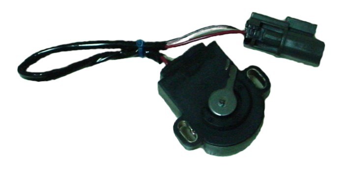
Throttle Position Sensor (TPS)
The TPS has an idle contact and a full throttle contact. The idle contact closes when the throttle valve is positioned at idle and opens when it is in any other position. Proper adjustment of the TPS is beteen 0.4 and 0.6 volts.

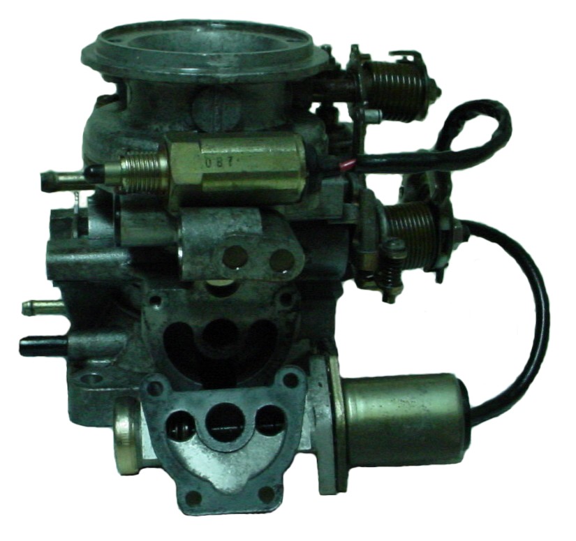
Throttle Body and Related Components


Swirl Control Valve (SCV)
The intake manifold houses a swirl control valve in each passage way of each cylinder. During idling and low engine speed, the valve closes to increase the velocity of airflow to each cylinder. This also promotes fuel vaporization and produces a swirl in the combustion chamber.

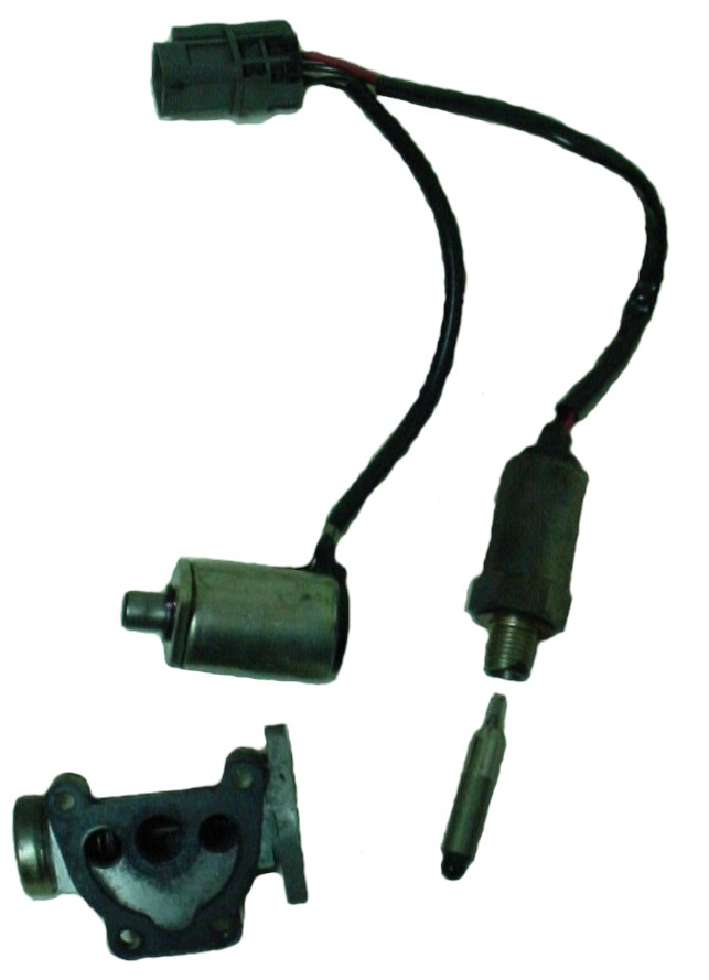
Idle Air Control Valve (IACV)-Auxiliary Air Control (ACC) Valve and Idle Air Adjusting (IAA) Unit
This unit controls the idle speed at a preset value under various conditions.


Crankshaft Position Sensor (CKPS)
The CKPS is located in the distributor, under the rotor. It monitors engine speed and piston position, and sends signals to the ECM to control fuel injection, ignition timing and other functions.
Cap & Rotor
Because of the increased voltage and spark duration, the distributor cap and rotor is replaced more frequently. The points are cleaned at least once every 2-3 weeks.
Tips
Location of the PCV Valve

Self Diagnostics
Mode I - Exhaust Oxygen Sensor Monitor
Use Mode I to determine if the Oxygen Sensor is functioning properly.
- Warm the engine to normal temperature.
- Run the engine above 2000 RPM under no load while looking at the ECU.
- Make sure the GREEN LED goes on and off more than five times during ten seconds at 2000 RPM.
- If the number of flashes are not more than five, replace the oxygen sensor. If the LED does not flash, check the sensor's circuit.
Mode II - Mixture Ratio Control Monitor
Use Mode II to determine if the air/fuel mixture is cycling correctly.
- Warm the engine to normal operating temperature.
- Turn the dial on the ECU fully clockwise (or if you have a switch, turn it on).
- After the LED flashes twice, turn the dial fully counter clockwise (or turn the switch off).
- Run the engine above 2000 RPM under no load while looking at the ECU.
- If the RED LED blinks simultaneously with the GREEN LED, the air/fuel mixture is cycling properly.
- If the RED LED stays off, the mixture is more than 5% rich.
- If the RED LED stays on, the mixture is more than 5% lean.
- If the RED LED stays on or off above 2000 RPM, complete the diagnostics before beginning repairs.
Mode III - Stored Fault Code Reporting
Use Mode III to retrive all stored trouble codes in memory.
- Turn the ignition switch on, but do not start the engine.
- On the ECU, turn the diagnostic mode selector screw fully clockwise (or if you have a switch, turn it on). Wait until the LED flashes 3 quick bursts, then turn the screw fully counter clockwise (or turn the switch off).
- The check engine light will begin to flash trouble codes. Red flashes are units of ten and green flashes are units of one. (red-3 flashes, green-1 flash = code 31) Note all codes until it begins to loop.
- To clear all stored codes, turn the screw fully clockwise (or turn the switch on). Wait until the LED flashes 4 quick bursts, then turn the screw fully counter clockwise (or turn the switch off). To retain the codes in memory, simply turn the ignition off.
KA24E Codes:
- 11 Crankshaft Position Sensor Circuit
- 12 Mass Air Flow Sensor Circuit
- 13 Engine Coolant Temperature Sensor Circuit
- 14 Vehicle Speed Sensor Circuit
- 21 Ignition Signal Missing in Primary Coil
- 31 Engine Control Unit (ECU)
- 33 Oxygen Sensor Circuit
- 41 Air Temperature Sensor Circuit
- 43 Throttle Position Sensor Circuit
- 55 No Malfunctions
Complete list of Codes for other models:
- 11 Crank Angle Sensor/Camshaft Position Sensor
- 12 Air Flow Meter/Mass Air Flow Sensor
- 13 Engine Coolant Temperature Sensor
- 14 Vehicle Speed Sensor
- 21 Ignition Signal
- 22 Fuel Pump
- 23 Idle Switch
- 24 Throttle Valve Switch
- 25 Idle Speed Control Valve
- 28 Cooling Fan Circuit
- 31 ECU
- 32 EGR Function
- 33 Heated Oxygen Sensor
- 34 Knock Sensor
- 35 Exhaust Gas Temperature Sensor
- 36 EGR Control-Back Pressure Transducer
- 37 Knock Sensor
- 38 Right hand bank Closed Loop (B2)
- 41 Intake Air Temperature Sensor
- 42 Fuel Temperature Sensor
- 43 Throttle Position Sensor
- 45 Injector Leak
- 47 Crankshaft Position Sensor
- 51 Injector Circuit
- 53 Oxygen Sensor
- 54 A/T Control
- 55 No Malfunction
- 63 No. 6 Cylinder Misfire
- 64 No. 5 Cylinder Misfire
- 65 No. 4 Cylinder Misfire
- 66 No. 3 Cylinder Misfire
- 67 No. 2 Cylinder Misfire
- 68 No. 1 Cylinder Misfire
- 71 Random Misfire
- 72 TWC Function right hand bank
- 73 TWC Function right hand bank
- 76 Fuel Injection System Function right hand bank
- 77 Rear Heated Oxygen Sensor Circuit
- 82 Crankshaft Position Sensor
- 84 A/T Diagnosis Communication Line
- 85 VTC Solenoid Valve Circuit
- 86 Fuel Injection System Function right hand bank
- 87 Canister Control Solenoid Valve Circuit
- 91 Front Heated Oxygen Sensor Heater Circuit right
hand bank
- 94 TCC Solenoid Valve
- 95 Crankshaft Position Sensor
- 98 Engine Coolant Temperature Sensor
- 101 Front Heated Oxygen Sensor Heater Circuit right hand bank
- 103 Park/Neutral Position Switch Circuit
- 105 EGR and EGR Canister Control Solenoid Valve Circuit
- 108 Canister Purge Control Valve Circuit
Check or replace the sensor(s) and related components corresponding the list of stores trouble codes.
Mode IV - Switch Operation Monitor
Use Mode IV to determine if the Throttle Position Sensor (TPS), Starter circuit and/or Vehicle Speed Sensor (VSS) are in proper working order.
- Turn the ignition switch on, but do not start the engine.
- Turn the dial on the ECU fully clockwise. After the LED flashes 4 times, turn the dial fully counter clockwise.
- Make sure the RED LED is turned off.
- Make sure the RED LED turns on when depressing the gas pedal. If not, check or replace the Throttle Position Sensor.
- Make sure the RED LED turns on when turning the ignition key the START position. If not, check or replace the starter.
- Drive the vehicle with the ECU unbolted and within view. Make sure the GREEN LED turns on when speed is 12 MPH or more. If not, check or replace the Vehicle Speed Sensor.
Mode V - Real Time Diagnostic Function
Use Mode V to determine if the Crankshaft Position Sensor (CPS), Mass Air Flow Sensor (MAFS) and/or Ignition signal are working properly.
- Start engine.
- Turn the dial on the ECU fully clockwise.
- After the LED flashes 5 times, turn the dial fully counter clockwise.
- Make sure LEDs do not flash for 5 minutes when racing or idling the engine.
- If it flashes, count the number of flashes, turn engine off, and see the following 3 paragraphs.
- Perform real-time diagnosis insepction and repair or replace malfunctioning part if present.
- If LEDs do not flash for 5 minutes, turn engine off.
If the RED LED flashes 3 times for 1.5 seconds, check the Crankshaft Position Sensor. Check the harness continuity at CPS when the engine is stopped. Inspect the harness for dust and clean if necessary. Check the pin terminal at ECU for bends and remove them as necessary. Reconnect harness and recheck continuity. During real-time diagnosis, tap the harness connector or component and check if trouble code is displayed. If so, replace terminal.
If the GREEN LED flashes twice-3 times for 0.5 seconds, check Mass Air Flow Sensor. Check the harness continuity at MAFS when the engine is stopped. Inspect the harness for dust and clean if necessary. Check the pin terminal at ECU for bends and remove them as necessary. Reconnect harness and recheck continuity. During real-time diagnosis, tap the harness connector or component and check if trouble code is displayed. If so, replace terminal.
If the GREEN LED flashes 4 times for 0.2 seconds 3 times, check the ignition signal. Check the harness continuity when the engine is stopped. Inspect the harness for dust and clean if necessary. Check the pin terminal at ECU for bends and remove them as necessary. Reconnect harness and recheck continuity. During real-time diagnosis, tap the harness connector or component and check if trouble code is displayed. If so, replace terminal.
Future Plans
Performance Cam
Port & Polished Heads
ECU Upgrade
Performance Underdrive Pulleys
Electric Fan
Links
Accell
Fender Bender International
Jim Wolfe Technology
K&N
MagnaFlow
MSD
Optima
PaceSetter


