130 AMP 3G "SMALL CASE" ALTERNATOR
The benifits of installing a more powerful alternator are numerous. a higher output alternator puts out more current, therefore less drain on your battery. It was painfully obvious that this was a needed modification, as the test car's headlights would dim at idle. Thank you underdrive pulleys! Also, as modifications progress, a highr output alternator is more than capable to handle increased loads placed on it by the addition of things like an electric fan, high output ignitions, and stand alone engine controllers. A new alternator is almost a critical addition once you enter the realm of high output stereo systems also. Installing a 3G alternator is fairly simple.
To complete the installation you'll need the following tools :
- Soldering gun
- Solder
- Wire cutters
- Wire stripper
- Pry bar or LONG screwdriver
- basic socket or combo wrench set
- Lighter
- Electrical or polyken tape
- Plastic convolute ( not required )
- Locktite 242 ( not required )
- Flat file, Dremel, or die grinder ( Not needed if using March alt brkt )
- Multimeter ( not NEEDED, but very handy )
I've done several 3G installations using an alternator for a 94-95 Mustang into a fox bodied car. This was my first experience with
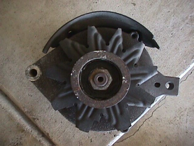
Mr. Alternator small case 3G.
The case of the alternator comes with an optional powdercoating that really makes it stand out in the crowd.
The alternator also comes with a stator wire and connector and two insulated terminals. Installation is easy and can be completed in 1-2 hours depending on your level of experience ( especially in soldering! )
First thing to do is disconnect the negative battery cable and remove the accessory drive belt. The belt can be removed by prying on the tensioner to remove the tension on the belt, then the belt can be slipped off of the alternator pulley.
Once that's done, remove the stock wiring from the old alternator. One of the factory connectors will be reused, the shorter connector with 2 rounded corners. Be careful not to crack it on removal. The other longer "spade" type connector will not be used so it's faster and easier to just cut the wires at the connectors.
Next, unbolt the 2 bolts holding the factory alternator in place. This will allow you to pivot the alternator back and forth in it's bracket to remove it.
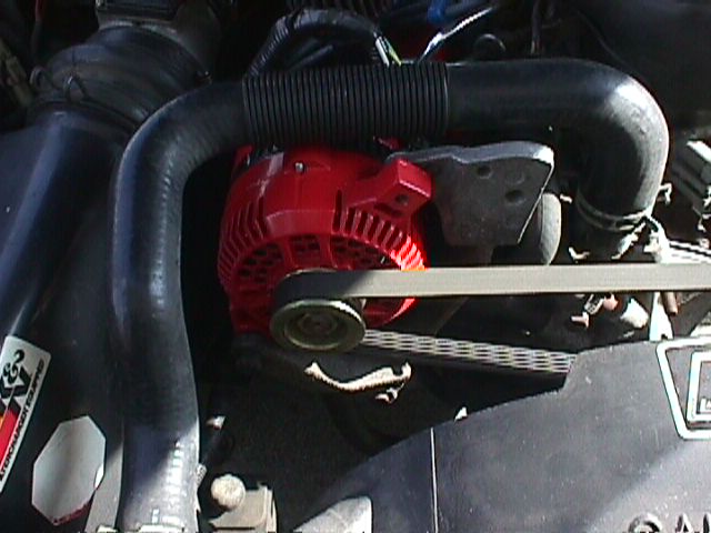
Now, trial fit the new alternaotr into the bracket. You'll have to hold the upper radiator hose out of the way to get a good view of where ( if any ) interference will be. On this car, there was a slight interference between alternator and bracket at the lower inboard alternator case bolt boss. The contact was minor, and 30 seconds with a dremel on high speed fixed it.
![]()
![]()
Once the bracket has been clearanced ( if needed ), you can bolt the alternator in place. A new bolt will be needed for the top hole.
You can reuse the bottom bolt. At this point, once it has been verified that there is no interference, pull the bolts back out, locktite them and torque them down.
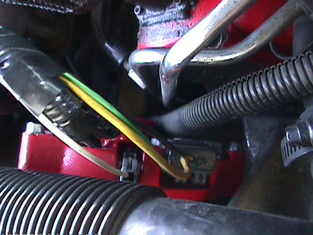
Now for the electrical portion. There were two connectors attached to the stock alternator, a longer one with "spade" type terminals and a shorter connector with 2 rounded edges. On the rounded connector there is a white wire. Cut this wire at about 3-4" from the connector. This is where the supplied stator wire will be soldered on. The stator wire is the supplied length of white wire with a grey plastic connector.
In the pictures below, there is a green wire, a yellow wire, and the center stator wire which has been covered in black shrink wrap. This is the wire you'll be soldering onto.


The rounded connector can now be plugged into the new alternator.
Now move onto the wires that came from the "spade" connector. There are 2 thicker 12 gage wires. Each of these gets crimped and soldered into one of the supplied insulated terminals. These have yellow insulated end in the piture below.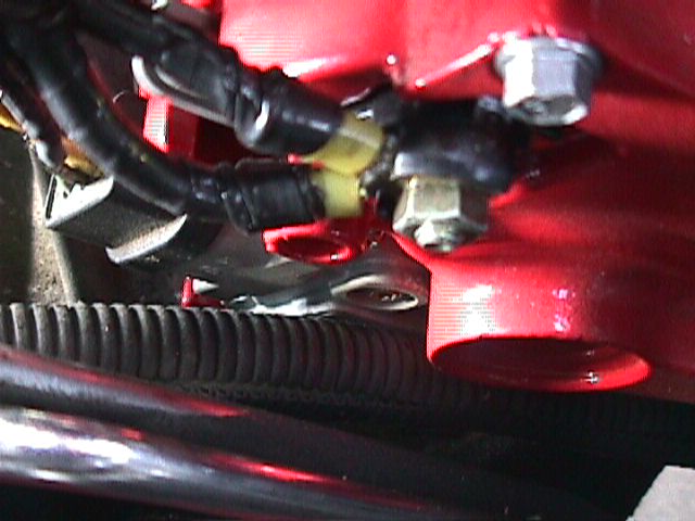
That's it!
Now reconnect the battery and reinstall the belt. A quick voltage check across the battery terminals should read 12-13volts. Start the car. Now there should be 14+ volts.
The finished product looks great and after 2 weeks, has performed perfectly!

You can contact Mr. Alternator by clicking their name here,or at the addres or phone number below: