
This is a cleaning procedure for CD-changers that fail to play a CD-disk after loading it properly and unsuccessfully scanning all tracks and for CD-changers that may play a CD-disk but skip tracks, particularly when driving on bumpy roads.
Preliminary step
Remove the CD-changer from the boot (no picture).Step 1
| Remove four top screws of the top cover as shown here. | 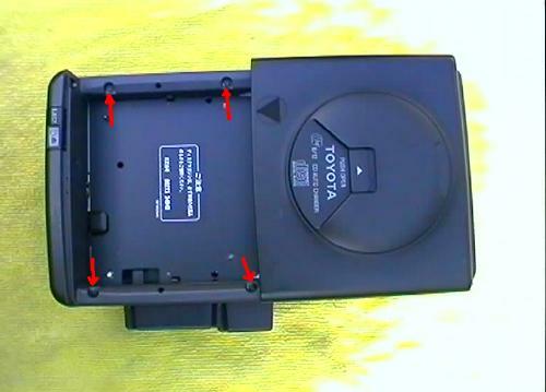 |
Step 2
| Remove another screw of the top cover from the short side. | 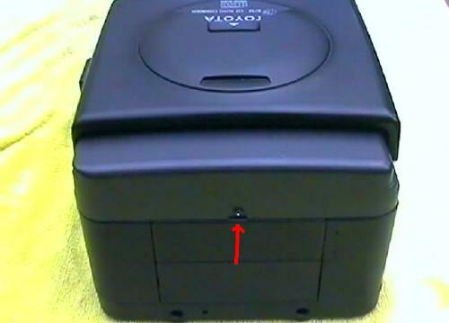 |
Step 3
| Remove two screws of the bottom cover from one side of the changer. |  |
Step 4
| Remove four screws of the bottom cover from the bottom of the changer. | 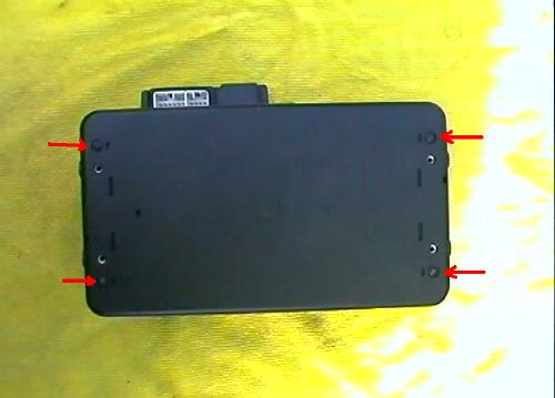 |
Step 5
| Remove two screws of the bottom cover from the other side of the changer and 5 screws securing the connector cover on the same side. | 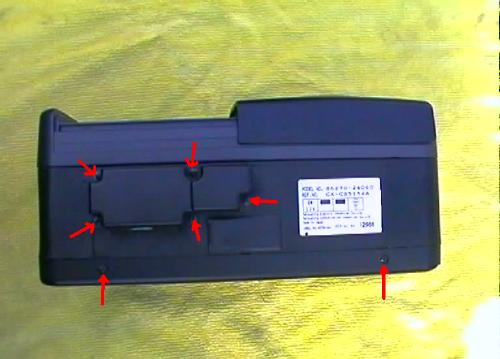 |
Step 6
| Connector cover removed. | 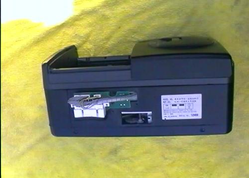 |
Step 7
| Unplug two wire connectors and remove two screws holding a small connector circuit board. | 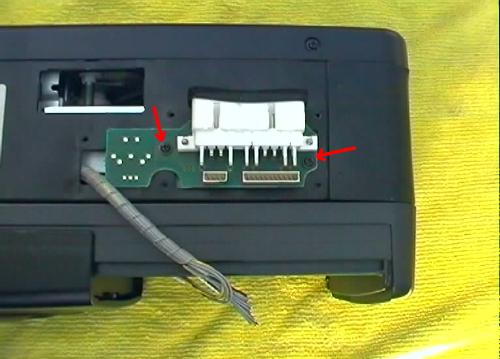 |
Step 8
| Connector circuit board removed. | 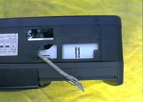 |
Step 9
| Lift up the top cover all around the main body of the changer. | 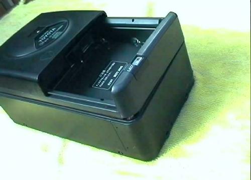 |
Step 10
| Top cover of the changer removed. | 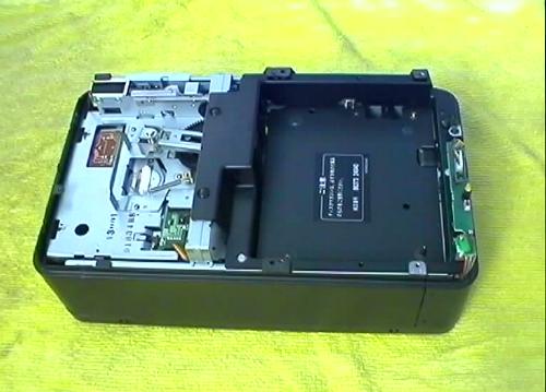 |
Step 11
| Remove one screw holding the earth cable near the yellow light. | 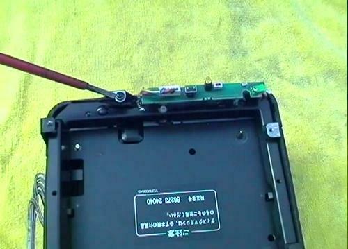 |
Step 12
| Lift up the main cover from the bottom cover along the long sides of the changer. | 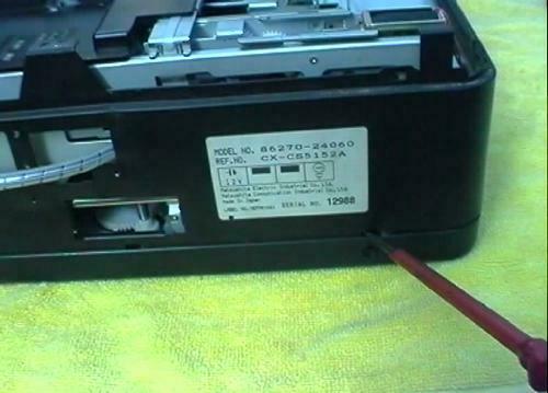 |
Step 13
| Lift up the main cover from the bottom cover at one short side of the changer. | 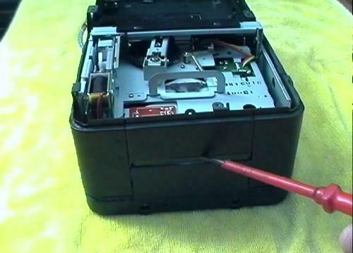 |
Step 14
| Lift up the main cover from the bottom cover at the other short side of the changer. | 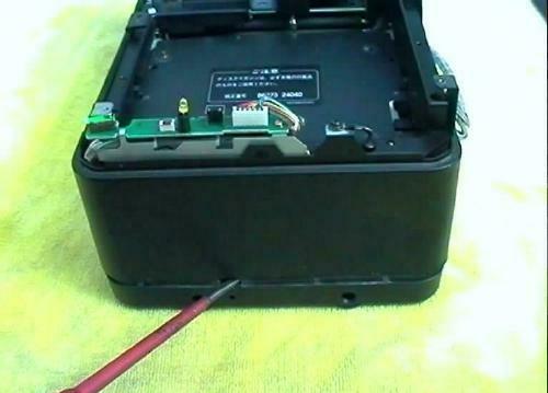 |
Step 15
| The main cover of the changer removed. Now, remove two screws of a plastic plate on the short side. | 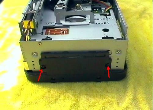 |
Step 17
| The plastic plate and bottom cover removed. The changer has been turned upside down - please check next step for an important note. | 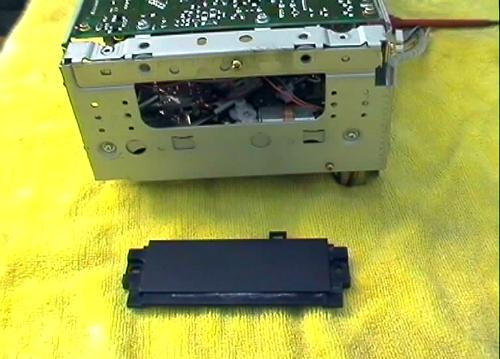 |
Step 18
| When turning the changer upside down make sure the side of the changer with the yellow light is well supported so that the changer does not rest on the light, otherwise the LED would become bent. | 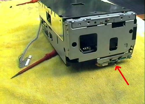 |
Step 19
| The changer upside down with the bottom cover removed, exposing the shiny metal shield plate. | 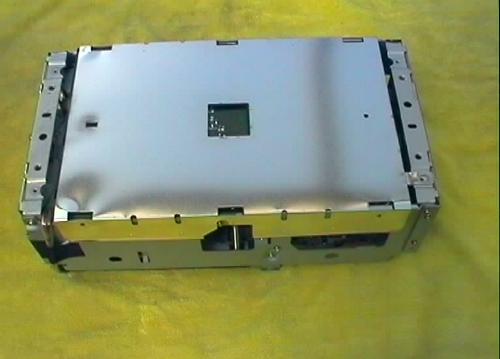 |
Step 20
| Lift up the metal shield plate and the black plastic sheet under the shield plate. (Picture shows the plastic cover, shiny metal shield and black plastic sheet, next to the changer). | 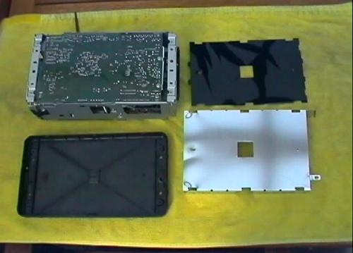 |
Step 21
| Remove 5 screws holding the main printed circuit board. | 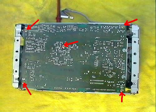 |
Step 22
| Use pair of pliers and straighten up the two metal tabs (as shown) to release the printed circuit board from the chassis. | 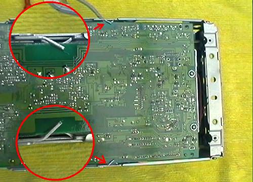 |
Step 23
| Turn the changer on its side as shown and carefully lift the printed circuit printed board from the chassis at one side only. To not try to fold the board flat at this stage, just open up a gap to get access inside the changer. | 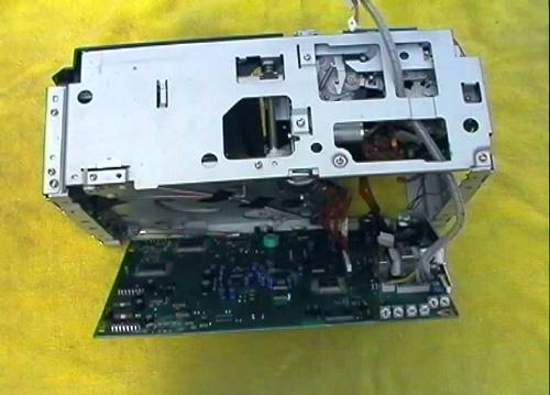 |
Step 24
| Disconnect the flat cable connector as shown. |  |
Step 25
| Fold the board away from the chassis so that it rests flat on the workbench. | 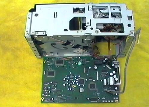 |
Step 26
| Underside of the laser pickup suspension assembly. | 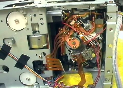 |
Step 27
| Underside of the optical head (laser pickup lens). | 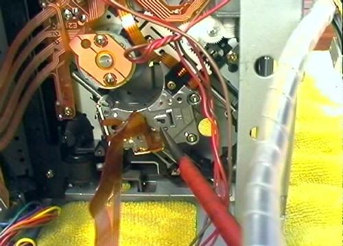 |
Step 28
| Motor for driving the optical head (laser pickup lens) on its sled. Note the polarity of the motor - when power is connected in this way the sled will move away from the spindle to the outside edge of the CD disk. When polarity is reversed, the sled will move towards the spindle. | 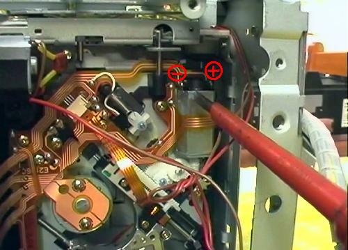 |
Step 29
| A battery pack 4x1.5 AA = 6V used to power the motor in order to move the sled for cleaning the pickup lens. Power is applied directly to the contacts of the motor where its polarity is shown in Step 28. | 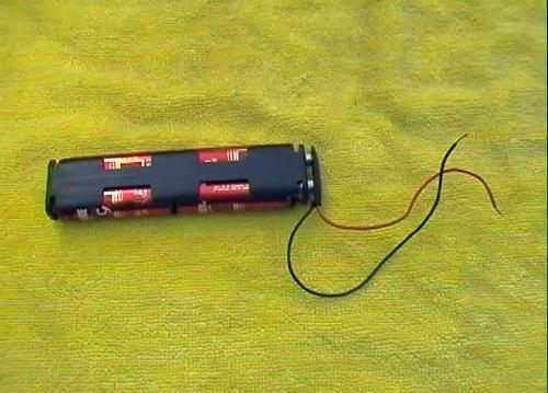 |
Step 30
| The optical head (underside shown) was moved on its sled in direction away from the spindle. The end of travel was reached as can be seen from the position of the pinion on the rack. | 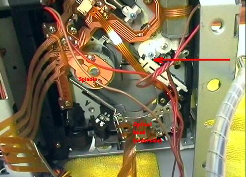 |
Step 31
| Temporarily return the printed circuit board in the chassis so that the changer can be laid flat again. There is no need to re-connect the flat cable to its connector as the work is not yet finished inside the changer. | 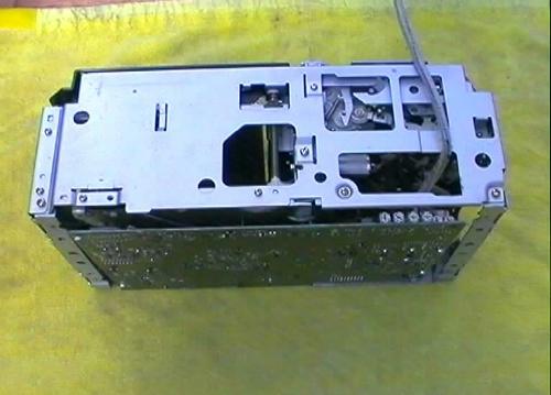 |
Step 32
| Laser pickup lens shall be cleaned through this hole. | 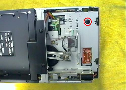 |
Step 33
| The laser pick up lens is visible inside the hole. | 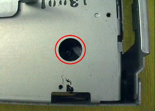 |
Step 34
| Medical grade Isopropyl alcohol will be used for cleaning the lens. |  |
Step 35
| Using a cotton tip dipped in alcohol the lens is cleaned by gentle strokes from side to side. It is a delicate assembly suspended in vertical and horizontal directions for focus and tracking adjustments and the cleaning must be done by just touching the surface of the lens without any pressure. | 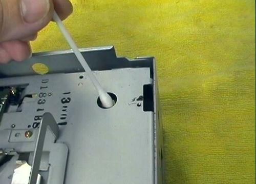 |
Step 36
| Returning inside the changer, the rack and pinion gear and the worm gear of the motor can be cleaned with a fine brush dipped in alcohol to remove any dirt. These parts should be lubricated again using a special grease (as used in repairs of VCR and similar equipment), sold in electronics supplies stores. Example is a German product called "Lager Fett, product No. 5143", sold by the Wagner Electronics Service in Sydney. Generally only a small amount of lubricant should be used. | 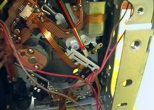 |
Step 37
| When cleaning the gear it is useful to move the optical head sled to the opposite end of its travel - near the spindle by applying power to the motor (with reversed polarity). | 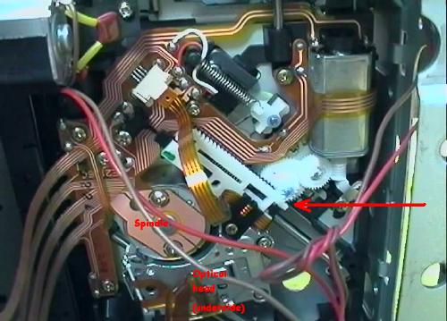 |
Step 38
| It is interesting to note the design of the rack and pinion gear. In order to eliminate any free-play the designers used two separate racks (white and black) placed side by side in a scissors arrangement, similar to a Toyota engine timing scissors gear setup. The two racks are preloaded by a longitudinal spring clearly visible in this picture. | 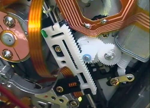 |
Step 39
| Assembly of the CD-changer is the reverse of the dis-assembly procedure (no picture). |
NOTE:
If the cleaning of the laser pickup lens and mechanism does not cure the skipping problems, then the only option is to replace the complete laser pickup assembly.
Email: info@startrade.org
