 ...
... ...
...The North American X-15 was a hypersonic rocket-powered aircraft operated by the United States Air Force and the National Aeronautics and Space Administration (NASA) as part of the X-plane series of experimental aircraft. The X-15 set speed and altitude records in the 1960s, reaching the edge of outer space and returning with valuable data used in aircraft and spacecraft design. Its highest speed, 4,520 mph (7,274 km/h), or Mach 6.7 was achieved in October 1967, when William J. Knight flew at an altitude of 102,100 feet (31,120 m), or 19.34 miles. This set the official world record for the highest speed ever recorded by a crewed, powered aircraft, which remains unbroken.
During the X-15 program, 12 pilots flew a combined 199 flights. Of these, 8 pilots flew a combined 13 flights which met the Air Force spaceflight criterion by exceeding the altitude of 50 miles (80 km), thus qualifying these pilots as being astronauts. The Air Force pilots qualified for military astronaut wings immediately, while the civilian pilots were eventually awarded NASA astronaut wings in 2005, 35 years after the last X-15 flight.
The X-15 was based on a concept study from Walter Dornberger for the National Advisory Committee for Aeronautics (NACA) for a hypersonic research aircraft. The requests for proposal (RFPs) were published on 30 December 1954 for the airframe and on 4 February 1955 for the rocket engine. The X-15 was built by two manufacturers: North American Aviation was contracted for the airframe in November 1955, and Reaction Motors was contracted for building the engines in 1956.
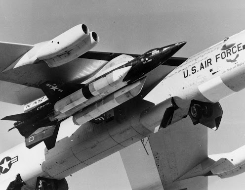
Like many X-series aircraft, the X-15 was designed to be carried aloft and drop launched from under the wing of a B-52 mother ship. Air Force NB-52A, "The High and Mighty One" (52-0003), and NB-52B, "The Challenger" (52-0008, a.k.a. Balls 8) served as carrier planes for all X-15 flights. Release took place at an altitude of about 8.5 miles (13.7 km) and a speed of about 500 mph (805 km/h).
The X-15 fuselage was long and cylindrical, with rear fairings that flattened its appearance, and thick, dorsal and ventral wedge-fin stabilizers. Parts of the fuselage (the outer skin) were heat-resistant nickel alloy (Inconel-X 750). The retractable landing gear comprised a nose-wheel carriage and two rear skids. The skids did not extend beyond the ventral fin, which required the pilot to jettison the lower two thirds of the fin just before landing. That fin section was recovered by parachute. A transport dolly was positioned under the fin for ground towing.
Three X-15s were built, flying 199 test flights. The first X-15 flight was an unpowered glide flight by Scott Crossfield, on 8 June 1959. Crossfield also piloted the first powered flight on 17 September 1959, and his first flight with the XLR-99 rocket engine on 15 November 1960. Twelve test pilots flew the X-15. Among these were Neil Armstrong, later a NASA astronaut and first man to set foot on the moon, and Joe Engle, later a commander of NASA Space Shuttle missions. The final X-15 flight occurred on 24 October 1968.
The second plane, X-15-2, was rebuilt after a landing accident on 9 November 1962 which damaged the craft and injured its pilot, John McKay. It was lengthened by 2.4 feet (73 cm), had a pair of auxiliary fuel tanks attached beneath its fuselage and wings, and a complete heat-resistant white ablative coating was added. This plane was renamed the X-15A-2 and went on to set the speed record of Mach 6.7.
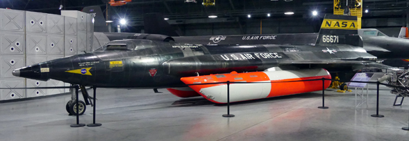
As an Air Force “Brat” growing up just outside Barksdale AFB in Bossier City, Louisiana, I was fully aware of the X-15 and Space programs and followed them closely. I think the X-15 is really cool looking, second only to the SR-71. It’s hard to believe that its first flight was only 14 years after the end of World War II. I’ve seen both X-15s on static display – one at the Smithsonian Air and Space Museum and one at the National Museum of the United States Air Force where I took the above color photo.
While building this model, I watched the film “X-15” (1961) which includes actual NASA and U.S. Air Force footage of the X-15 program. The cast includes Charles Bronson and Mary Tyler Moore and is narrated by Jimmy Stewart. The complete film can be viewed free on YouTube.
Facts and General Characteristics of the X-15A-2:
Contractor: North American Aviation
Total built: 3 (all variants)
Crew: 1
Wingspan: 22 ft. 4 in. (6.8 m)
Length: 52 ft. 5 in. (16 m)
Height: 13 ft. 3 in. (4 m)
Weight: Empty 14,600 lbs. (6,622 kg), Gross 34,000 lbs. (15,422 kg)
Power plant: 1 × Reaction Motors XLR99-RM-2 liquid-fueled rocket engine, 70,400 lbf (313 kN) maximum thrust.
Speed: 4,520 mph (7,270 km/h)
Range: 280 miles (450 km)
Service ceiling: 354,330 ft. (108,000 m)
Facts and General Characteristics of the Model:
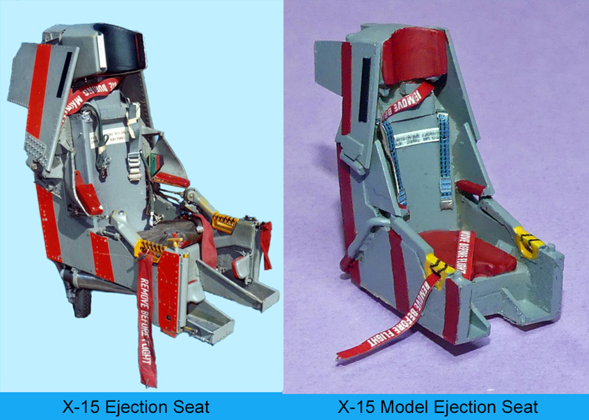
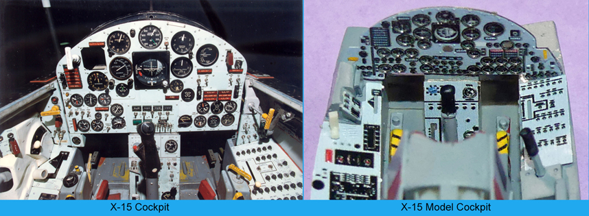
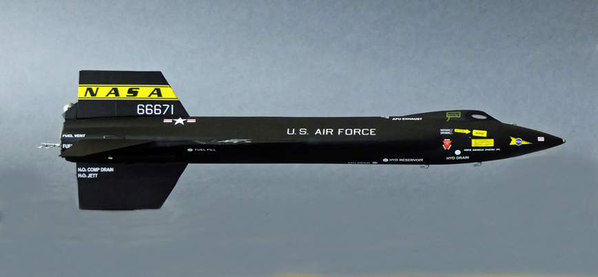
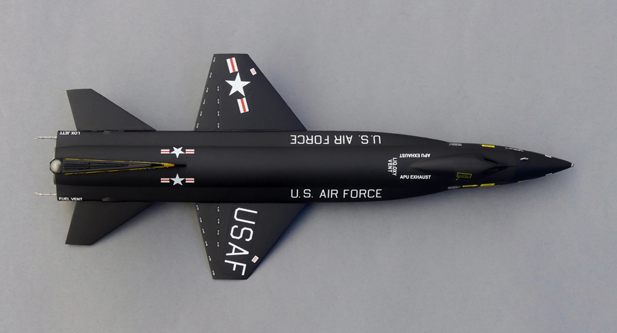
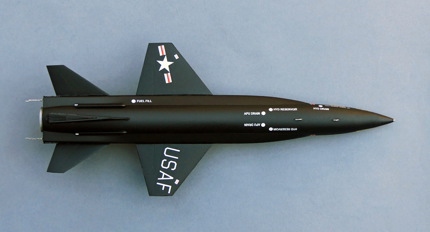
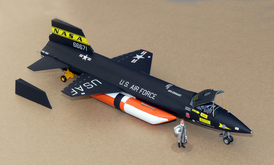
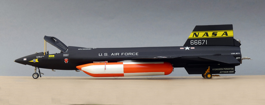
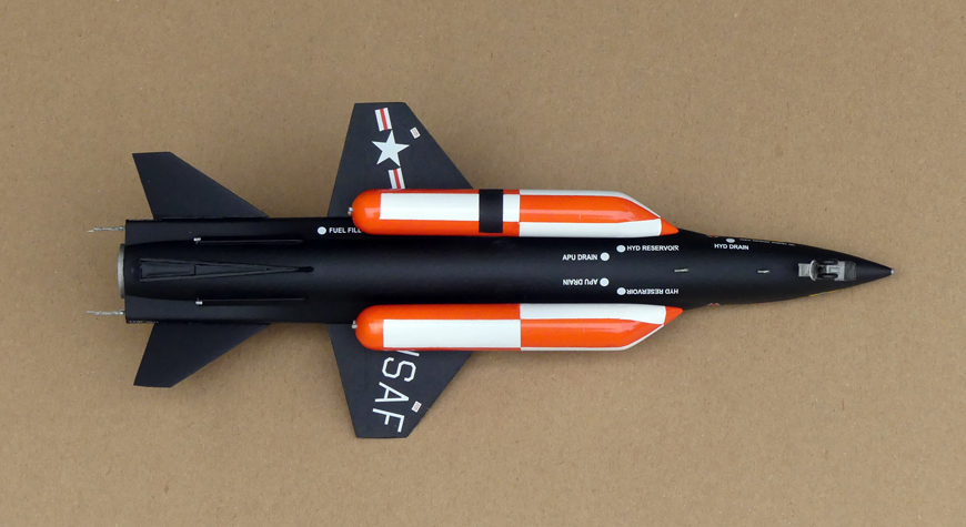
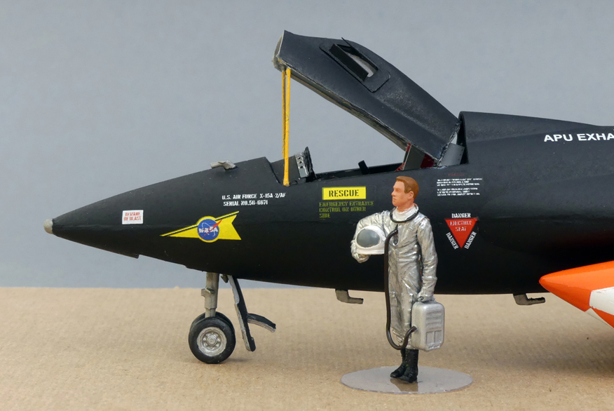
The paint and markings of the model depict the X-15A-2 56-66671 as it appeared on 2 November 1965. I added the optional wind screen on the left canopy window as it is now attached on the actual X-15 displayed in the National Museum of the United States Air Force. The final model depicts the aircraft resting on the transport dolly and with the auxiliary fuel tanks, but minus the bottom section of the ventral wedge-fin stabilizer. The rear landing skids are retracted. I also manufactured two canopy posts to hold up the canopy so the cockpit can be viewed. Before I finished the model in the ground configuration, I photographed it in the flight configuration with the full ventral wedge-fin stabilizer but without the auxiliary fuel tanks which weren’t used on every flight.
Manufacturer: Special Hobby, MPM Production s.r.o., Czech Republic
Scale: 1/48
Wingspan: 5.6”
Length: 13.8”
Height (ground transport configuration): 3”
Parts: 96 (53 resin including pilot and transport dolly, 28 plastic and 15 photo-etched)
Decals: 47
Hours to build and paint: 30.5
Mistakes/Problems:
1. The instruction illustrations were vague. There were no locater pins/holes on all parts except for the main wings so it was hard to determine part placements. I had to refer to many actual photos of the X-15 to figure out how to fit some of the parts.
2. Almost none of the plastic and resin parts fit correctly. I had to do a lot of filing and filling gaps.
3. This was the first time I worked with resin parts and while they are generally more detailed than plastic parts, several required separating, i.e. cutting them from a base. I broke a few parts while trying to cut them from the bases.
4. While the photo-etched parts add a lot of realism, many of the cockpit parts were just too tiny to handle or were broken off when handling them.
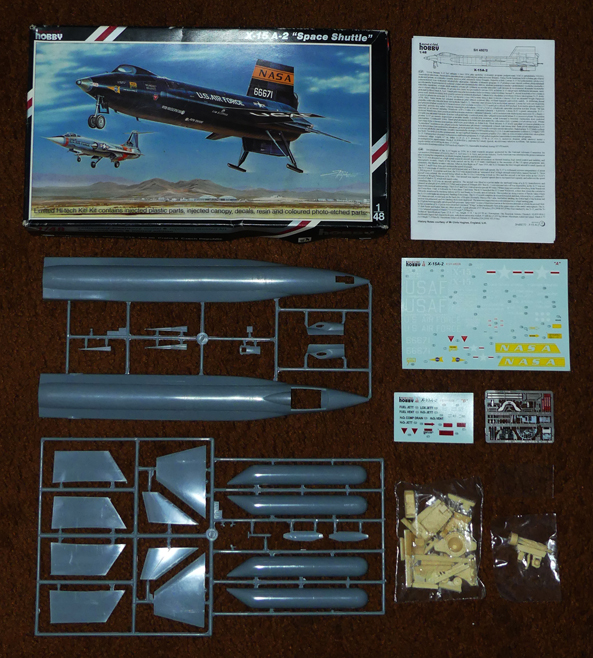
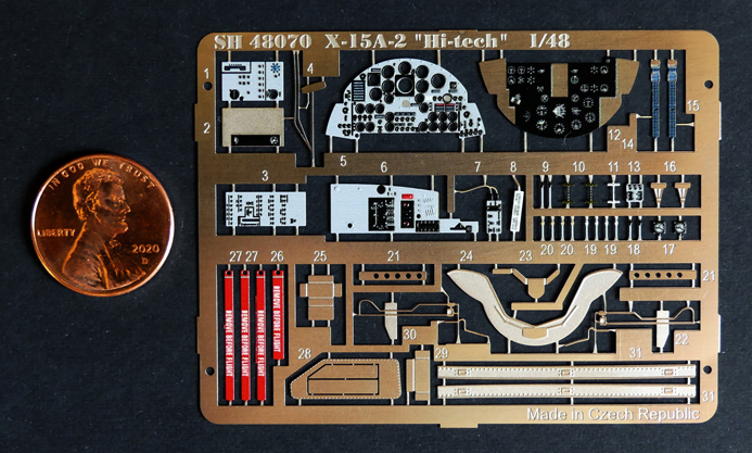
Photo-etched Parts
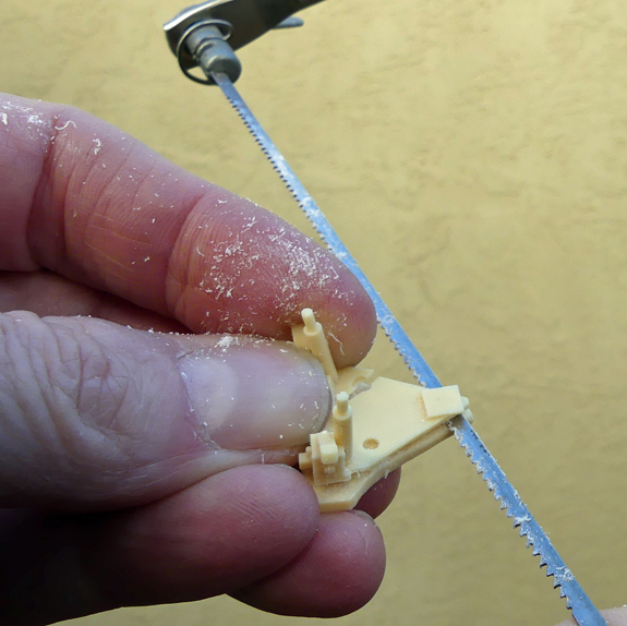
Cutting a resin transport dolly part from its base. You can see I broke this part.