 |
The amount of weight was calculated by first determining the gross weight at the G loading desired. For this test, we used a gross of 1,250 pounds at 4 G's. This comes to 5,000 lbs.
I'm told the canard carries 65% of the load, so the gross of 5,000 lbs was factored at 65%, which gives us a total weight of 3,250 lbs.
I decided to divide the canard into 14" sections so I could use sand bags 'right off the shelf'. They measure 12" in width. With the canard laid out in 14" sections, and with the elevator in place, I then calculated the surface area of each station. Since the canard tapers, each station's surface area is progressively smaller, starting from the root.
Once the surface area for each station was determined,
I calculated a total wing surface area of approximately 38 square feet.
By dividing the weight of 3,250 lbs by the 38 sqft of wing area, I got a
wing loading of approximately* 87 pounds per sqft. Using this number and
multiplying it by the wing area of each station, I arrived at the total
amount of weight required at each station. This worked out to be a little
under 200 lbs at the wing tip to a little over 400 lbs. at the root.
*All calculations made during the stress test were precise.
I'm using estimated numbers here for simplification.
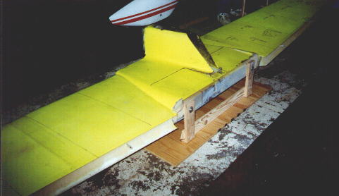
I chose to make a platform as opposed
|
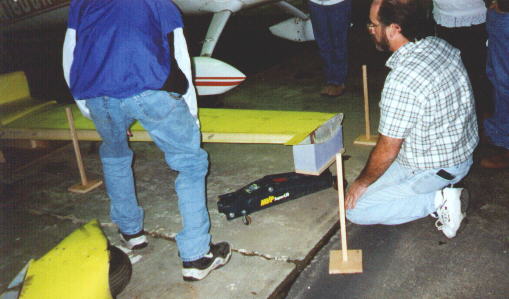
The canard was checked for level and
|
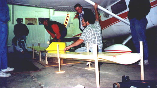
Since this was an EAA chapter meeting, I was the
speaker for the evening.
|
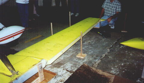
Marker sticks were placed at both
|
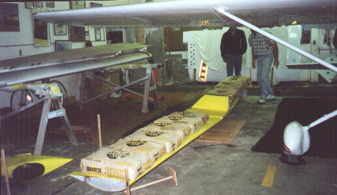
With each marker located, alignment
|
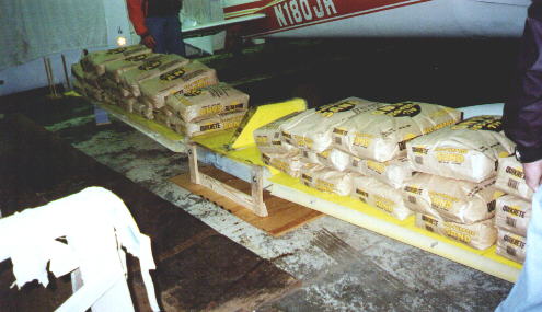
Then we began to load the sand in place. |
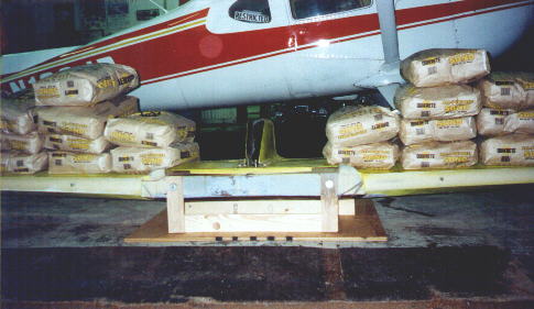
The sand was loaded equally. |
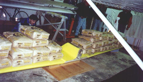
After all of the 'off the shelf' bags were
|
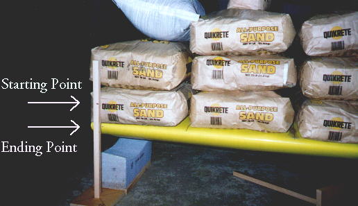
After all loading was completed, the
|
We were not going for catastrophic failure. All we needed to see is if the canard would return to it's original shape, after being subjected to 4 G's of weight. If it would not have returned to it's origional shape, it would have been a failure, and a new canard would be in order. Thankfully, this is not the case for this canard.
The plan is to install the Mark II steel gear legs, basically as outlined in the newsletters.
Esse site foi ideia de Patrick Panzera de Hanford California EUA.