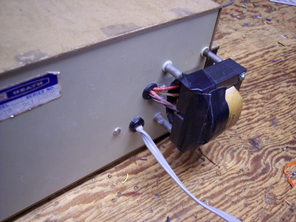
If after reducing the oscillator amplitude, disabling the meter, disabling the square-wave generator, improving the power supply, and lowering the distortion in the amplifier, the distortion reading is still too high you need to move the power transformer outside the case.
The transformer is rather close to the oscillator components particularly the frequency determining capacitors. If its field is inducing 50 or 60 cycle hum into any part of the oscillator circuit a harmonic distortion analyzer will read this frequency along with the harmonics and give a higher than true distortion figure. Short of operating the entire thing from batteries, (5 9-volts would do the trick,) moving the transformer seems to be the only solution.
Not only has the transformer been moved outside the case but it is grounded to the case at only one point to avoid a path for the magnetic field to induce currents into the metal case. Some eddy currents may still be induced but I'm a firm believer in preventing trouble if at all possible.

- Unsolder all of the transformer leads making notes as to where each one goes. Be sure to note how the transformer primary is wired. The primary connections are the solder terminals under the chassis.
- Remove the 4 nuts that hold the transformer to the chassis.
- Lift the transformer out of the chassis.
- Remove the screw that holds the grounding lug and terminal strip on which the fuse is mounted. Be careful not to lose any of the small washers.
- Save the hardware and push the terminal strip slightly away from the panel.
- Carefully measure the spacing of the transformer mounting studs.
- Using the hole from which you just removed the screw as the lower left corner drill holes for all 4 mounting studs. Refer to the photo above.
- Drill a 9/64 inch hole in the back panel on the other side of the line cord strain relief from the terminal strip with the fuse.
- Drill a hole for the grommet and install it. Size this hole to fit the grommet you have.
- Obtain the following parts.
- 4 ¾ inch 6-32 tapped spacers.
- 6 number 6 Nylon shoulder washers of the type used to insulate transistors.
- 1 or more number 6 flat metal washers to equal the thickness of the thin part of the shoulder washers.
- 4 6-32 x ½ screws.
- Thread the four spacers onto the four studs on the transformer and tighten them with pliers.
- Cut two lengths of hookup wire long enough to reach from outside the case to the place where the transformer primary connections went. Allow some extra length, wire is cheap.
- Twist these two wires together to form a twisted pair.
- Solder the twisted pair of hookup wire to the 120 or 240 input terminals depending on where you live in the world. Be sure to wire the primary for 120 or 240 volts as it originally was.
- Wrap vinyl electrical tape around the transformer to cover the terminals to protect them from being shorted to metal surfaces or giving someone a shock.
- Enlarge 3, and only 3 of the holes in the back panel to fit the thicker part of the shoulder washers. Do not enlarge the hole where you removed the screw.
- In the following, do not tighten any of the screws until all are started.
- Insert shoulder washers into each of the large holes, one from each side, and start a 6-32 x ½ screw from the inside of the oscillator and into the spacer on the transformer on the outside.
- From the inside insert a 6-32 x ½ screw through the terminal strip foot and grounding lug with any washers that were there before.
- Slide the metal flat washer under the fourth spacer and push the screw through the panel, washer, and into the spacer.
- Make sure all shoulder washers are seated properly and tighten all 4 screws that hold the transformer. Do not over tighten the three that are through nylon washers. Put your effort into the one that is through the metal washer.

Measure the distortion again. Still not low enough? You're out of luck because that's all I have to suggest.
- Pass all transformer wires through the grommet. Route the primary wires below the chassis through the hole where the transformer was, cut them to length, and connect them to the terminal strip you added as shown in the photo.
- Connect the wires from the power on/off switch and the indicator lamp to this same terminal strip. The wires which go off to the left are the ones to the indicator lamp and the ones exiting at the bottom of the photo go to the switch. Solder all connections.
- Solder the red and yellow wires back to the power supply board as they were before.
- Carefully inspect your work and do some basic continuity testing to be sure you haven't created any short circuits.
- Introduction and Modifications 1, 2, and 3.
- Modification 4, Power Supply Regulator.
- Modification 5, Decreasing Distortion in Amplifier.
- Modification 6, Mounting Power Transformer Outside the Case. (You are here.)
The day that the Heath company closed its doors
was a sad day indeed for electronics home brewers.
Before it existed there was nothing in the world like it,
It was never equaled by its wood-be competition,
And there will never again be anything like it.
HomeOr use your "Back" button to return to where you were.
This page last updated April 15, 2006.