In these modern times it's not easy to find parts. Some of you may be afraid of winding coils (it took me many years to get over helixaphobia. However my investigations have led me to the inescapable conclusion that winding coils is the best way.That's what I thought three years ago. I have found that some of the old coil sets are still available. The P-C70-A from Antique Electronics Supply works just as well and maybe a little better than the coils you can wind. Winding coils is an interesting experiment and you may want to do it just for the fun of it. If you would rather skip all the fun you can. Some additional instructions have been added below.
It's really not that hard and it is guaranteed to be painless. I have devised a method in which you use Double Stick (stickem on both sides) Scotch Tape to hold the wire in place while you wind the coil. One of the most frustrating things about winding a coil is what happens when you let go of it. The double stick tape prevents this from happening. To learn how to wind your own coils click here.
If you don't have a variable capacitor you will need to buy one. If you would rather not wind your own coils there are ferrite antennas and antenna coils for sail. Click here to learn what to buy and where to buy it.
Another source is to take a transistor radio apart to salvage the tuning capacitor and ferrite antenna. It's kind of fun tearing up one of those disgusting little things and you might learn a thing or two in the process. The parts you get are of limited usefulness which is why I really don't recommend it. If you have the time and the inclination give it a try. Just click here.
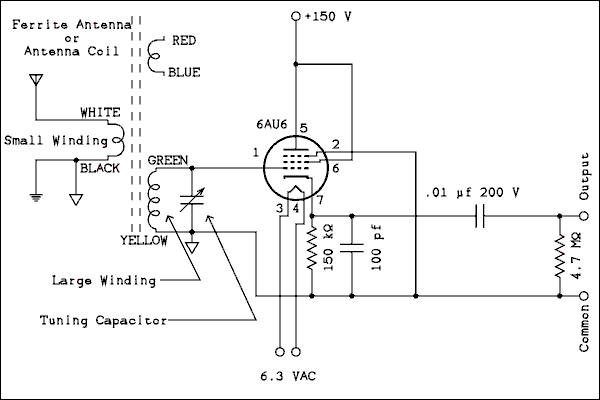
A variation of the plate detector is the infinite impedance detector. This circuit normally uses a triode tube but if we connect the screen grid to the plate and the suppresser grid to ground the tube will behave like a triode.
The large value of resistance in the cathode places the tube very close to cut-off. A signal applied to the grid is rectified by the tube. This circuit can also be used as an AC or RF voltmeter.
If you are using the Hammond antenna coil from AES connect it as follows. Pins 2 and 4 to ground. Pin 1 to the tuning capacitor and grid of the tube. Pin 3 to the antenna. This runs counter to the connections recommended by the manufacturer but I know what I am doing. Try connecting a 33 pf capacitor between pins 1 and 3. Refer to the Crystal Set article. See how the performance changes with and without the capacitor. 
For a verbal description click here.
You can also use this circuit with modern stereo headphones by connecting the primary of a 10 k ohm to 2 k ohm audio transformer in parallel with the 4.7 meg ohm resistor. Also see the Crystal Set article referred to above.
Like the plate detector this one takes no power from the tuned circuit. Unlike the plate detector the audio signal is taken off the cathode of the tube. That makes it a cathode follower which can have better linearity than the common cathode circuit. The books say that it does better with very strong signals and they are right.
The selectivity is good but the audio output is not as high as with the plate detector. I haven't tried any of these tube circuits with headphones. I'm not going to do everything for you. If you want to know, try it for yourself.
If you would actually like to BUILD a one tube radio in some sort of permanent form this is one I would recommend. Have fun, more to come.