
Figure 1 Simple 0 to 500 Volt Adjustable power supply.
For a verbal description click here.
In this article I will first examine what constitutes a bench power supply. Next I will discuss variability, regulation, and the combination of both to make a regulated variable supply. Next I will describe various circuit configurations on the block diagram level for regulating and adjusting the DC output of a power supply. Finally I will provide circuit diagrams from various hobbyist sources and successful commercial products.A Bench Power Supply.
A bench power supply needs to provide any and all voltages that may be needed on the bench for breadboarding and testing electronic circuits or troubleshooting a malfunctioning instrument. With such broadly defined requirements you could go crazy listing what you might need.
- 3.5 and 5 volt DC at high current for logic and CPU circuits.
- 9 V to 36 V DC low current well regulated and filtered for small signal transistor and integrated circuits.
- 25 V to 100 V high current for IC and transistor power circuits.
- 50 to 500 VDC at up to 200 mA for plate and screen circuits of moderate power vacuum tube circuits.
- 0 to -100 VDC for vacuum tube grid bias.
- 300 to 2500 volts at 1 A for high power vacuum tube circuits such as transmitters.
- 1000 to 5000 VDC at a few mA for cathode ray and photo multiplier tubes.
- A wide variety of voltages ranging from 1.5 to 120 volts at currents ranging from 50 mA to 10 A AC or DC for filaments and heaters of vacuum tubes.
A single unit with all that would be bigger than the bench it services. So clearly we need to place limits on our power supply design. The site we are on is called Fun With Tubes so we can eliminate the transistor and logic part of the monster. Work with high power RF or AF circuits is a specialty among engineers so the high power part would consist of a special supply for that purpose alone. Same goes for engineers specializing in the fields that use CRTs and PMTs so they are gone. The complexity of filament and heater voltage switching can be eliminated because most work with tube circuits is done with tubes that have 6.3 or 12.6 volt heaters. The occasional tube circuit needing different heater/filament voltage can be accommodated by a temporary lash up employing a filament transformer or a transistor power supply. So here is what we really need.
- 50 to 500 VDC at up to 200 mA for plate and screen supplies of moderate power vacuum tube circuits.
- 0 to -100 VDC for vacuum tube grid bias.
- 6.3 and 12.6 VAC at a few amps for tube heaters.
We now have a manageable power supply that can sit on a bench or its equipment shelf. Also it won't require a fork lift to place it there or 3 phase power to juice it up.
Variability and Regulation.
Many people make the casual assumption that if a power supply has variable voltage output, it must also be regulated. If you think that, focus your baby blues on figure 1 below the next heading. Not all adjustable power supplies are regulated and not all regulated power supplies are adjustable.Variable Voltage Power Supplies.
The simplest form of variable voltage, also known as adjustable, power supply is shown in figure 1.
Figure 1 Simple 0 to 500 Volt Adjustable power supply.
For a verbal description click here.
Load Regulation = 100 (VNL - VFL ) / VNL Where VNL is the voltage with no load and VFL is the voltage at full load.
And while we are defining terms line regulation is defined this way,
Line Regulation = 100 (VLMAX - VLMIN) / VLMAX Another form of making an adjustable voltage power supply involves the use of tubes as shown below.

Figure 2 0 to 400 Volt Adjustable power supply using Tube(s).
Regulated Power Supplies.
An automatic regulator consists of 4 basic parts.
- Reference.
- Comparing Device.
- Error Amplifier.
- Controller.
The block diagram is shown below.

Figure 3 Block diagram of a generalized linear regulator.
This diagram applies to any analog or linear automatic regulator device.

Figure 4 Diagram of Simple Voltage Regulator.
Variable Voltage Regulated Power Supplies.
The power supply in figure 4 can be improved by moving the B negative point from the cathode of the vr tube to the cathode of the amplifier tube. This makes it better but not perfect.

Figure 5 Adjustable Regulator with Improved Range.
Determining the Minimum and Maximum Output Voltage.
You can always build a power supply and then run tests on it to see how high and how low the output voltage can go. Most likely you have a set of rough specifications in mind and if the finished power supply doesn't meet or surpass them you are going to feel disappointment and probably some additional emotions.There are two factors that affect the maximum voltage. They are (1) The ripple valley voltage of the rectifier/filter, and (2) the minimum plate voltage of the pass tube(s).
Ripple Valley Voltage.
You may never have heard of "ripple valley voltage". An exception would be if you have studied my on line textbook titled "Electronics for Non-Engineers" or you enrolled in my course at Western Kentucky University in the years I was teaching there. The almost universal use of integrated circuit voltage regulators has made it a very important concept yet few people have ever heard of it and fewer still understand it.

Figure 6 Schematic of Rectifier and Filter with Output Waveform.
i = C dv/dt. I = C ΔV / Δ t Ripple Valley Voltage = VP - Δt I / C Ripple Valley Voltage = 350 x square root of 2 - 8 x 10-3 x 0.2 / 220 x 10-6 = 488 V.

Figure 7 Plate Characteristics of 6AS7G/6080/6080WA, one section.
Maximum Output Voltage.
What we need to do is to determine the voltage drop across the pass tube for zero grid voltage and the maximum specified current. If we use one tube the current in each section will be 1/2 of 200 mA or 100 mA. The voltage drop for 100 mA looks to be pretty close to 50 volts. For two tubes the current for each section is 50 mA and the voltage appears to be about 1/3 of 50 volts which is about 17 volts. Given the valley voltage of 488 volts for a single 6080 the maximum output voltage is 488 - 50 = 438 volts. For two tubes the maximum output voltage is 488 - 17 = 471 volts. For a production unit the value of the filter capacitor could be somewhat reduced for lower cost. For a single hobbyist unit a few tens of cents won't make that much difference.Maximum Pass Tube Dissipation.
Think we are doing pretty good at meeting our specifications? Think again. The maximum plate dissipation for the 6080 is 13 watts per plate or 26 watts for both sections. I didn't find any information about derating when the tube is used with both sections in parallel. So for a plate current of 200 mA the maximum plate to cathode voltage is 130 volts. (Note: We earlier calculated the ripple valley voltage to be 488 volts and the peak to be 495 volts. The average of these two values is 491.5.) That means when the plate is at an average voltage of 491.5 volts the lowest the cathode can safely go for a load current of 200 mA is 491.5 - 130 = 361.5volts. Of course the current can be derated for lower voltages. For example for a current of 100 mA the maximum plate to cathode voltage is 26 watts / 100 mA = 260 volts. That will bring us down to 231.5 volts. At this point we have already exceeded the maximum plate voltage of 250 volts but it does appear that maximum plate voltage ratings were made to be exceeded.This makes the case for using two tubes in parallel. The plate dissipation is now 52 watts and the maximum plate to cathode is now 260 volts which gives an output of 231.5 volts. At our minimum output voltage of 50 volts the current must be derated to 118 mA.
Minimum Amplifier Tube Plate Voltage.
The absolute minimum output voltage of our power supply is set by a combination of the pass tube and the amplifier tube. Let's say we are going to use a 6AV6 as the amplifier tube.

Figure 8 Plate Characteristics of 6AV6, Triode Section.
This graph is somewhat similar to the one in figure 7 but the curves
are leaning more to the right. The zero volt curve is slightly convex.
Let's Do It With Pentodes.

Figure 9 Same Regulator as Figure 5 But Using Pentodes.
Triode vs Pentode Operation Of the Pass Tubes.
Here are the plate characteristics for the 6L6 connected as a triode.

Figure 10 Triode Characteristics of 6L6GA.

Figure 11 Pentode Characteristics of 6L6GA.
Maximum Output Voltage.
The maximum output voltage corresponds to minimum plate voltage of the pass tube. Looking at the 6L6 curves we see that for a grid voltage of zero we can get down to about 20 volts for 50 mA per tube. Note that the scale is 15 volts per horizontal division. But there is more going on than just the plate voltage and current. The screen current for 20 volts on the plate is about 65 mA. If the screen voltage remained at 100 250 volts the screen dissipation would be 16.25 watts. Maximum for the 6L6GC is 5 watts so the screen would be melted down in pretty short order. But the voltage will not be constant at 250 volts because there is a 1 k ohm resistor in the filtering circuit. Let's say that the screen current rises to 20 mA. The drop across the 1 k resistor will be 20 volts giving a screen voltage of 230 volts. The operating conditions of the tube have now changed and the curves are no longer valid. But they are all we have. 20 mA at 230 volts gives a power of 4.6 watts. That's about as high as we should go. It's hard to see but it looks like the dashed line crosses the 20 mA line at 60 volts. So we can safely take the plate voltage down to 60 volts. The ripple valley voltage calculated above was 488 volts so we can get the output voltage up to 488 - 60 = 428 volts. So we can meet the maximum voltage specification of 400 volts with some to spare.Minimum Output Voltage.
If it were possible for the plate voltage of the 6AU6 to get down to zero the cathode of the pass tubes could get down to 31 volts. If the grid voltage is zero the cathode is 31 volts more positive for a current of 5 mA. It is impossible to say what would happen at lower currents. I would need my own vacuum tube curve tracer to evaluate the 6L6 at small values of cathode current. I haven't built one yet. Here are the plate characteristics for the 6AU6.

Figure 12 Plate Characteristics of 6AU6A.
Maximum plate dissipation.
The maximum plate dissipation for the 6L6GC is 30 watts so for four of them it is 120 watts. Max plate volts = 120 W / 200 mA = 600 volts. Not to worry. Our basic unregulated power supply has an optimistic voltage output of 500 volts so even if the output voltage would go to zero we could not over dissipate the 6L6GC plates. So we have essentially met our specifications. 50 to 400 volts at 200 mA.Under conditions of very light loading the voltage probably wouldn't get down to 50 volts and under heavy loads at low voltage it probably would go considerably below 50 volts. If we were designing a commercial unit our boss would consider the design a failure and our job could be in jeopardy. But we are retired and working for ourselves. We are not going to fire us.
Voltage Adjusting Resistor String.
This circuit has something in common with all of the power supply circuits to be subsequently described and discussed. This is the way in which the voltage is adjusted. Not with a pot connected as a pot but connected as a rheostat. Figure 9 is repeated here for your convenience.
Figure 13 Figure 9 Repeated.
Adjusting the Voltage All the Way To Zero.
There can be considerable debate over the issue of how low the voltage of a power supply needs to go. No one in their right mind is going to use a tube power supply to power a 5 volt logic circuit. But how many times have you done something that sounds crazy when you tell someone about it later. Don't answer that. Sometimes we find ourselves in a hurry or with a defective transistor power supply and we have to do something foolish.But I think the main reason is marketing. The adjustable power supply buyer whether hobbyist or professional engineer has come to expect an adjustable power supply to go all the way to zero. Sellers have taught buyers to want supplies that go to zero and buyers have taught sellers that they can't sell a power supply unless it goes all the way to zero. This is kind of a chicken and egg thing where we can't figure out which came first. Necessary or not, adjustable power supplies have to go to zero when the voltage knob is turned fully counter clockwise. In a following section we will see what Heath and Eico did to get the voltage to go all the way to zero.
There Is Another Way.
In the diagrams to follow the comparison circuit and amplifier will be represented as an op amp (operational amplifier) rather than a circuit made up of tubes. In this day and time everyone who dabbles in, plays with, or works in the field of, electronics knows how an op amp behaves in a circuit. Think of it as an op amp built with tubes. Once upon a time they actually were. To get you oriented here is how we would draw the circuit of figure 5.

Figure 14 Figure 5 but with an "op amp" replacing the 6AU6.
Floating the Reference, the Op Amp, and their Power Supply.
I first encountered a circuit like this when someone brought me a 0 to 3000 volt, that's right, 3kV, power supply to repair. When I opened it up I found one tube and a circuit board with a number of transistors on it. I think the number was somewhere between 10 and 20 but it has been a long time. These weren't special transistors. In fact they were in sockets and most of them had been replaced with 2N706s. As it turned out there were a couple of PNP transistors and one of them was bad. I bought a GE replacement from the local TV parts supply house and the power supply was back in business. The above mentioned circuit board contained a discrete version of an op amp. Here is how they mixed 3 kV and small signal transistors without blowing anything up.

Figure 15 Wide Range Power Supply.
Now I will guide you around this diagram to prevent you from getting lost.
- There are two bridge rectifiers in the diagram. Look at the lower one. I hope you know that when you connect a bridge to a transformer secondary that has a center tap you get a positive voltage between the tap and the diode cathodes and a negative voltage between the tap and the diode anodes. Note that the cathodes, with some capacitive filtering supply the positive rail of the op amp while the anodes supply the negative rail.
- The center tap of the op amp supply connects to the positive output terminal of the regulator, cathode of the pass tube. Just follow the line and if you don't take any wrong turns you'll get there.
- The noninverting input connects to this same point.
- The inverting input connects to the junction of the 400 k ohm rheostat and a fixed 10 k ohm resistor.
- The bottom end of the divider, other end of 400 k ohm rheostat, connects to the negative output terminal.
- The other end of the 10 k ohm resistor connects to the reference, a 10 volt zener diode. Note that the reference is derived from the positive floating power supply.
- The output adjustment is set to 400 volts.
- The center tap of the op amp power supply will be at 400 volts.
- The positive op amp rail will be at +418 volts.
- The negative op amp rail will be at +382 volts.
- Noninverting input, 400 volts.
- Inverting input, 400 volts. (Note: According to rule one of op amps if the feedback loop is closed and working properly and the amplifier is not defective, the voltage at the inverting input will equal the voltage at the noninverting input when measured with a 3-1/2 digit DMM.)
- Output of amplifier, 360 to 380 volts depending on load.
- Screen grid of pass tube, 650 volts.
- Plate of pass tube 500 volts.
- Cathode of zener, 410 volts.
- The output adjustment is set to 400 volts.
- Positive output terminal, 0 volts.
- Center tap of op amp power supply, 0 volts.
- Positive op amp rail, +18 volts.
- Negative op amp rail, -18 volts.
- Noninverting input, 0 volts.
- Inverting input, 0 volts.
- Output of amplifier, -20 to -40 volts depending on load.
- Screen grid of pass tube, +250 volts.
- Plate of pass tube +100 volts.
- Cathode of zener, +10 volts.
But Back to Tubes.
A really good regulated supply needs a high gain amplifier with a differential input. Such amplifiers are harder to design than you might think. We would like to put the amplifier on a floating power supply as shown above but the amplifier needs to be DC coupled and tubes do not cascade easily because there is no PNP tube to put between stages to bring the level back down after the first stage. Multi kilovolt supplies have to float the DC amplifier because it isn't practical to change the voltage on the plate of a tube from less than 100 volts to 2 or 3 kV. As you will soon see both HP and Fluke allowed a common receiving tube to have in excess of 600 volts on its plate.Excessive plate voltage on the pass tube will lead to excessive plate dissipation so something must be done about it. In many power supplies the unregulated supply is variable along with the output voltage setting to minimize dissipation in the pass tube(s).
The HP712B has a continuously variable voltage adjustment with a voltmeter for achieving the proper voltage. To do this they have ganged a very ordinary looking pot with a variable transformer. That looks as incongruous as it sounds. The HP engineers have worked things out so the plate voltage of the 6L6GC pass tubes stays a few hundred volts ahead of the output voltage as the output is turned up from 0 to 500 volts. This is possible because the rotation angle of the typical variable transformer is greater than the rotation angle of the typical pot. The mechanical stops are set to coincide at the maximum (fully counter clockwise) setting. At the minimum voltage end the pot stops the rotation before the variable transformer voltage has come to zero. Because of the large knob used HP has provided hard mechanical stops independent of the pot or variable transformer.
The Fluke 407 takes a more common approach. The coarse setting of the output voltage is a rotary switch that goes from 0 to 500 volts in 50 volt steps. One wafer of the switch selects resistors that make up the 400 k ohm pot in figure 15 but the other wafer selects taps on the power transformer to keep a reasonable voltage on the plates of the pass tubes. There is a fine adjustment which is a pot covering 0 to 55 volts. Only the 50 volt step switch changes taps on the transformer. There is also an ultra fine adjustment that covers 0 to 0.55 volts. The pots are connected as rheostats.
The word "floating" used in the preceding is somewhat misleading. The power supply for the amplifier isn't really free floating, it is tied to the output and rises and falls with it. It means that the amplifier and the reference voltage do not need to feel the full voltage of the power supply. So a transistor circuit can be used to regulate 3000 volts by controlling a single tube and you really could build a bench power supply with a 741 op amp although there are newer ones that have much better performance.
Commercial and Hobby Units.
I can't possibly round up every commercially produced power supply let alone all the circuits that were published in hobby magazines during the tube era. It's mostly a survey of what I know.The Heathkit IP 17.


Figure 16 Simplified Diagram of Heath and Eico Power Supplies.
Figure 17 Almost Complete Schematic Diagram of Heath IP17.
The HP 712B.

Simplified Circuit.

Figure 18 Simplified Diagram of Hewlett Packard 712B Power Supply
The -300 Volt Regulator.
The diagram below is a more detailed schematic of the -300 volt regulator.

Figure 19 Schematic Diagram of -300 Volt Regulator Circuit.
The 0 to 500 volt regulator.
The diagram below is a more detailed schematic of the 0 to 500 volt regulator.

Figure 20 Schematic Diagram of 500 Volt Regulator Circuit.
You should now be well prepared for the schematic diagram.
The Complete Schematic Diagram.

Figure 21 Schematic Diagram of Hewlett Packard 712B Power Supply.
For a verbal description of transformers, rectifiers, and filters, only click here.
The Fluke 407.

A Circuit From the ARRL Radio Amateurs Handbook.

Figure 22 Schematic of a Power Supply from the 1957 ARRL Handbook.
A Circuit Which I Designed and Constructed. It Works.
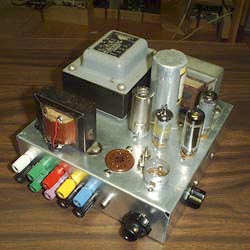

Figure 23 Schematic of My Own Design.
This was a project intended for those who were building my radio projects. It incorporates an audio amplifier and a power supply into the same compact chassis. The power supply circuit is essentially the same as figure 9. In the photo above the 6V6gt and 12AX7 audio amplifier tubes have been removed from their sockets. The transformer on the left front is the output transformer. The audio amplifier has enough gain to be used to amplify an electric guitar but would be more useful as a signal tracer. Full construction details are available at this location.
Conclusions.
It seems likely that a more compact and cooler running power supply could be made with silicon devices. The requirement for voltage measured in the hundreds of volts no longer eliminates this solution. BUT…THIS IS FUN WITH TUBES. I'm not going to tell you how to run your shop. You may build a power supply entirely of silicon devices if you like. You may use power tubes for the pass element and silicon devices as the reference and DC amplifier. Or you may go all tube. The choice is yours. I have tried to present the various options so you can make an intelligent choice. Good luck and above all have fun.