
Figure 1 General Setup for Sweeping an IF Transformer.
For a Verbal Description click here.
Almost from the invention of radio, engineers have wanted an easy way to see the frequency response of tuned amplifiers. If you attended any sort of electronics educational institution prior to about 1985 you probably performed a rather tedious lab experiment in which you set a signal generator to a frequency and wrote down the frequency and voltage in a chart and then moved on to the next frequency to obtain another data point. Then you took the data sheet back to your dorm and sat down with a piece of graph paper and a French curve to graph the data. If you didn't make any procedural errors such as reading the wrong scale on the voltmeter you would get a nice looking curve.While automatic frequency response plotters became available in the 1960s their cost was prohibitive for all but the largest universities and they certainly would never allowed mere students to use them in lab experiments. These devices were so far beyond the means of hams and other hobbyists that we couldn't even afford to read the catalog.
The development of two products changed all of that. They were the digital sweep function generator and the digital storage oscilloscope. While the introductory price of these items was still in 5 figures the prices slowly came down through the 1990s and the first decade of the 21st century. While there are Chinese made versions of these instruments available for around 50 dollars, as we will see, they are so lacking in features as to be next to useless.
The General Setup.
Figure 1 General Setup for Sweeping an IF Transformer.
For a Verbal Description click here.
Don't Sweep It Too Fast.
The maximum sweep rate is limited by the highest Q element inside the filter. When the frequency sweeps across the peak of a high Q element the high Q means that the ringing of the filter will come to the correct amplitude slowly. It's sort of like a flywheel. It takes a finite amount of time to get a flywheel spinning and it will continue to spin for a while after the driving source is removed. It's the same for a tuned circuit. As the frequency of a sweep generator slides across the resonant frequency of a resonator the amplitude of the response will follow the curve of the frequency response if the sweep is not too fast. If it is too fast the amplitude will not have time to build up to the maximum before the sweeper's frequency is sliding down the other side of the response curve. The result is an inaccurate representation of the overall response of the filter. (Note: The typical IF transformer only has two resonate circuits referred to as resonators. More complex LC filters, may have several resonators. Other types of filters such as crystal and mechanical filters will have many more resonators and they will have a much higher Q than LC filters.) The effects of this are that the peak will be shifted to the right of its actual frequency and the skirts of the curve will appear to rise and fall more slowly than they actually do.For the IF transformers in an AM broadcast receiver this time is quite fast because there are only two resonators and they have a relatively low Q. Sweep rates in the low to mid audio band can be used for these transformers. When mechanical or crystal filters need to be swept the rate must be kept below 10 sweeps per second. This is too low to be easily used with an analog oscilloscope. How a filter response to an amplitude modulated signal is determined by the overall bandwidth of the filter. When it is swept the Q of individual resonators in the filter determines how it responds to the sweeping frequency.
All three oscilloscope screenshots below were made using a Siglent SDG 5082 generator and a Siglent SDS 2202X DSO. The frequency scale is 10 kHz/div.

Figure 2 Sweep Rate of 1 MHz/sec.

Figure 3 Sweep Rate of 10 MHz/sec.

Figure 4 Sweep Rate of 100 MHz/sec.
The rate of 1 MHz/sec seems to be good. Rates lower than this give no improvement in the display. At first glance the rate of 10 MHz/sec looks as good but look closely at the rounded top of the yellow trace. There is just a little bit of sag on the right side as compared to the 1 MHz/sec rate. The 100 MHz/sec rate looks really bad. Obviously this rate is beyond the limit.
Setting Up For Sweeping, Practical Considerations.
The times 10 probes that go with any modern oscilloscope have low capacitance but it is still enough to detune an IF transformer. After you make all of the connections the alignment must be retouched a bit. Don't forget to ground the shield can of the transformer. Turn off the sweep function and set the generator to 455 kHz. Carefully adjust both tuning adjustments for maximum deflection on the scope. Adjust the two alternately to be sure to account for any interaction between the two adjustments.I have collected several function generators, I suppose for situations like this. I will now go through them giving detailed setup instructions and showing the results. Some cost more than others. I will start with the least expensive and work up to the most. The generators are,
- FeelTech FY3200S. eBay, $50.
- Siglent SDG 810. Circuit Specialists, $282.
- Siglent SDG 1025. Circuit Specialists, $319.
- Siglent SDG 5082. Circuit Specialists, $599.
Note: The last two digits of Siglent model numbers are the upper frequency limit of the generator in MHz.
Oscilloscope Setup, For all Generators.
Y axis, Ch1 and Ch2.
Vertical Range, 500 mV/div.
Vertical Position, Center of Screen.
Input selection, DC or AC.
Trigger.
Source, Ext/5.
Mode, Auto. If trace is unstable use Normal mode.
Level, +2.5V. Reduce to 0.5V if it won't sync.
Slope, Positive.
Coupling, DC.
Sweep.
Time, Depends on generator settings. 10 ms/div in this example.
Five div to the left of Center of screen.
FeelTech FY3200S
Below you will find setup instructions in English.
- Press the Ch2 button and use the left and right arrow keys and the knob to set the frequency to 0.00096kHz.
- Press the WAVE button once and the word SINE in the display will change to "SQUAR" (square).
- Press the PARAM button twice and change the AMPL (amplitude) to 5.0 volts.
- Press the Ch1 button.
- Press the SWEP (sweep) button twice and set the BEGIN FREQ (beginning frequency) to 405.00000 kHz.
- Press the SWEP button again and set the END FREQ (end frequency) to 505.00000kHz.
- Press the SWEP button again and set the TIME to 1s (1 second).
- Press the SWEP button again and the word STOP will appear in the low right of the display.
- Press in on the knob and the word STOP will change to RUN.
If you have connected the IF transformer correctly and set up your scope right you will see this pattern on the screen.

Figure 5 Sweep of IF Transformer With eBay Generator.
The first thing you will notice is the quantitization of the trace. This is unavoidable in digital devices however because we are analog creachers digital equipment for our use has been designed with small enough steps so we perceive it as if it were analog. The frequency steps in this generator are so large as to make it little more than a toy.
The trace of the frequency response will not appear in the center of the screen. If it does, go out and buy a power ball ticket. While the frequency of the square wave on channel 2 is the same as the sweep repetition frequency they are not locked together in phase. Their relative phase depends on when you start the sweep. You can repeatedly press the knob to stop and start the sweep until you get it where you want it.
The consequence of this is that the screen has no absolute calibration. If you pre tuned the transformer to 455kHz as described above you can have some confidence that the peak of the response is very close to 455 kHz. The relative calibration of 10 kHz per division is called into question by the need to set the frequency of the synchronizing wave on channel 2 to 0.96 Hz. This does not give me high confidence in the relative calibration either. The extra 4% might be accounted for as retrace time in an analog generator, a digital frequency generator should not require very much time to reset to the starting frequency. The scope picture below puts an end to all of this speculation.

Figure 6 Picture Showing Error in Relative Frequency Calibration.
The discontinuities in the purple trace at about 2 and a half horizontal divisions and exactly 13 divisions indicate the retrace points. The narrow spike makes them easy to find. The spike on the right exactly covers up the graticule line and the one on the left falls almost 10.4 divisions from it. And there's your 4% error. Looks like it's true, you get what you pay for.
Siglent SDG 810.
This procedure will be the same for any of the 800 series. The least expensive is the SDG 805 at $248 from Circuit Specialists.This change to this page is long overdue. My apologies to Steve who is a member of the Siglent staff. He was kind enough to contact me by email with the information on how to make the 800 series function generators deliver a sync pulse for triggering the oscilloscope. This eliminates the need for a second generator. The information is presented below which has taken the place of the original information which was not correct.I did not know that the left hand connector on the front panel of the SDG 8xx serves as either an input or an output depending on the settings of the generator's parameters. It is labeled "Sync Out/Ext Trig" but the font is so small I had missed this designation. I thought it was an input only. Even if I had known I don't think I would have found the setting in the menus. I will explain below so you won't have to go searching for it.

Figure 7 Using Only the SDG-810 to sweep an IF transformer.
For a verbal description click here
The generator's sweep time and that of the scope do not necessarily have to be the same although the scopes time must be longer than, or the same as, the generator's. The sweep time of the scope is not the time per division setting. It is that setting multiplied by the number of horizontal divisions. If you haven't noticed my scope has 14 horizontal divisions. I have seen DSOs with 12 divisions as well as the traditional 10.
If you want the frequency sweep to cover the full horizontal width of the screen the sweep time on the sweep generator must be the same as the time it takes for your scope to complete one horizontal sweep for the time/div setting you have chosen to use. I am using a setting of 10 ms/div which gives a total sweep time of 140 ms.
On the other hand there is no problem with setting the sweep time on the generator to 10 ms. The frequency span will only cover 10 divisions and the trigger point will be easier to set.
If you have the output impedance set to 50 ohms as I do you get twice the output value you set, unless you have a 50 ohm termination connected. If you have it set to Hi Z you will get what you set.
Scope and Generator Settings.
In the step-by-step instructions below I make frequent reference to the "soft keys". These are pushbuttons that instead of being hard wired to perform one specific function, can perform different functions under software control depending on the context. The keys are located next to the display screen and their functions are indicated by labels placed on the screen by the software. Pay close attention to these labels as there are no labels printed on the instrument's panel. The soft key labels appear only on the display screen.
- Set the scope sweep to 10 ms/div.
- SDG 810 settings.
- Press the soft key next to Amplitude.
- Rotate the knob until the amplitude value in the display changes. Use left and right arrows to move between digits.
- Alternatively, type the desired number on the numeric keypad. The soft key menu will change to allow you to enter the units you intend.
- Amplitude (actual output) 10 Vpp.
- Wave to sine. This is the power up default and is probably already set.
- Press the Sweep button. The soft key menu will change.
- The default for entry is sweep time. Use the keypad to set the desired value and soft key menu to set the units.
- Set the sweep time to either 100 ms, 140 ms or whatever suits your scope and your fancy.
- The next two soft keys down have two labels. The upper set are StopFreq, Stop Frequency, and StartFreq, Start Frequency. These two keys work together to set the respective frequencies. However, for using a linear sweep to sweep IF transformers it is easier to set middle frequency and frequency span MidFreq and FreqSpan.
- Press the key next to MidFreq and pressit a second time to highlight the word.
- Enter 455 on the numeric pad and press kHz to select the units.
- Press the key next to FreqSpan only once. Enter 100 kHz.
- Press the Utility key. The soft key menu will change.
- Press the Sync soft key, near the bottom. The soft key menu will change again.
- The State option, at the top, will be selected by default and will be set to either Off or On.
- If the word Off appears below the word Sync press the button next to them and it will change to On.
- If it is already on go to the next step.
- Press the Done soft key.
- Once set the State option will remain set.
- Connect the generator and scope to the IF transformer as shown in figure 7.
- You should see something like this. You may have to touch up the tuning of the transformer to get this display.
- If you are not getting anything check the output button. It should be lighted. I don't know how many times I have forgotten to turn on the output.
This is how your generator should look after you complete the setup.
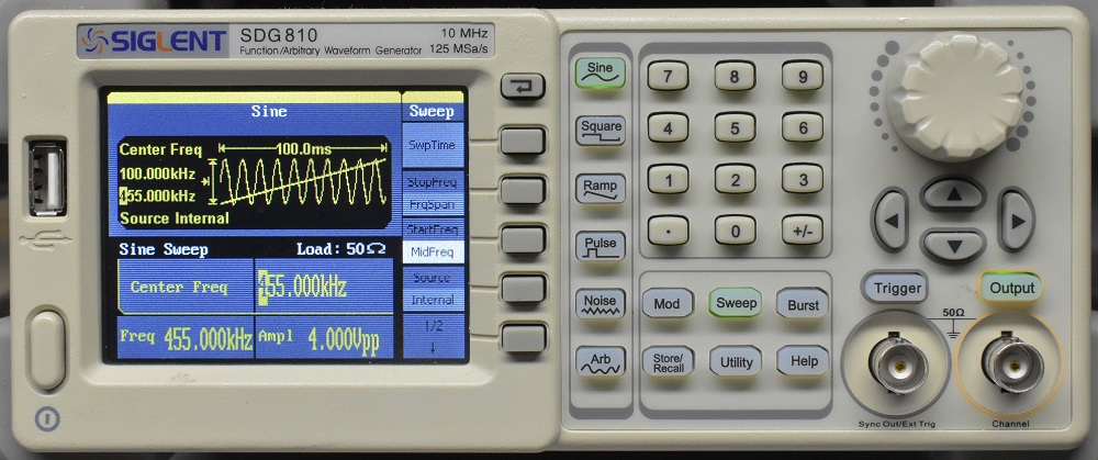
Figure 8 Resulting Screen for SDG 810.
Here is what you should see on your scope.

Figure 9 Trace of an IF transformer using the settings above.
Siglent SDG 1025, SDG 5082, and Other Two Channel Function Generators.
Once again I won't go into the details of setting up each generator. If you own one of the 1000 or 5000 series you will already know how to operate it. If you own a two channel generator of a different brand I don't know how to operate it so I can't tell you how.For these two generators the scope sweep remains on10 ms/div but you must change the trigger slope to negative.
Scope Settings.
Scope Sweep, 10 ms/div.
Trigger slope, Negative.
SDG 1000 or 5000 Settings.
Channel 1.
Wave, Sine.
Amplitude (actual output) 10 Vpp.
Sweep Time 140 ms. Set correctly for your scope.
Center Frequency, 455 kHz.
Frequency Span, 140 kHz. (Adjust for your scope to give a scale of 10 kHz/div). Channel 2.
Wave, Square.
Amplitude 5 Vpp.
Period, 140 ms. Set correctly for your scope.
Both of these generators use the setup shown in figure 1. The difference between these two generators and the one from eBay is that the phase relationship between the sweep control and the channel 2 square wave output is fixed and will be the same every time you set it up.

Figure 11 Picture Showing Frequency Sweep Retrace Point.
The two models of generator are not consistent with each other but each one is consistent with itself. This is no problem because the horizontal position control can be set for very good frequency accuracy.
In the picture above look at the purple trace between the vertical grid lines one and two. There is a discontinuity and a tiny spike where the frequency sweep arrived at the maximum value and was reset to the minimum frequency to begin another sweep. The retrace seems to take place in the width of one pixel. The sweep retrace on your DSO is just as fast. As the position control is moved to the left the retrace point will move off the left edge of the screen and will appear at the right. Depending on whether your scope has over scan or not you may be able to see the retrace artifact at both edges of the screen or you may not be able to see it at all. The point is that when the retrace occurs on the outside grid lines the calibration places 455 kHz at the exact center of the screen and each horizontal division is 10 kHz.
Conclusion.
This article can hardly be considered a comprehensive survey of sweep generators. I suppose that some of you think I am rich but I'm not that rich. If you have a sweep generator and you can't make it perform as shown here I may or may not be able to help you. That's the way it goes with long distance help. But if you want help contact me through the Fun With Tubes email list and I'll see what I can do.