|
High Voltage Hazard
CAUTION! The tails of a bobtail or half square are very hot with RF when you
are transmitting. They can cause severe RF burns. Be certain that any part of
the antenna that can be reached by people or animals is well insulated!
The vertical parts near the ground can be placed inside of loose-fitting
PVC plastic tubes. A length of 8-10 feet would be good. Do not overlook
this important detail!
New!
 An 80 meter LC Network (14K .jpg)
 Wound on a ceramic form
New!
A 40 meter LC Network (15K .jpg)
Built in a plastic ice cream box
The Enclosure
Tuning networks must be mounted in a weatherproof housing.
The coaxial capacitor, if used, should be sealed after tuning. Clear silicone
sealants such as GE RTV® or similar work well. Coil dope or varnish will
not do a good job. Use a good quality, high-voltage insulator for connecting
the antenna to the network inside.
For my 80m half square, I used an old aluminum milk box with a
weather-tight, hinged top. The insulator was a
large, ceramic feedthrough mounted in the side of the box. The
outside had about a 4 inch breakdown path, and inside the box
about 1 1/2 inches. The box had the original thermal insulation inside,
which probably improved the high voltage breakdown rating.
The coax connector was also mounted on the side of the box, and
short wires connected the box to a 3 by 5 foot piece of galvanized steel wire
cloth used as the counterpoise.
A suitable substitute insulator could also be made with sheet stock
covering the side of a metal box. Remove the metal except for a
narrow rim to mount the sheet to. A machine screw or threaded stud is passed
through the center. 1/4 inch diameter hardware would be a good choice here.
Use only materials with known good RF insulating qualities such as G-10
fiberglass epoxy, Plexiglass® acrylic, or Lexan® polycarbonate.
It should be thick for mechanical strength and have a large surface area for
good high-voltage breakdown. Double up thinner layers, if necessary.
Remember to space the inductor at least one diameter away from the sides
of a metal box to avoid reducing the coil Q and increasing power loss.
Note that while metal boxes are convenient to use, other materials can also
be used. Shielding is not required.
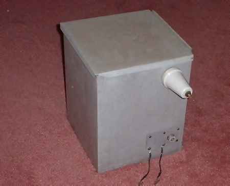
New!
An aluminum milkbox enclosure (7K .jpg)
Hinged lid, ceramic insulator,
SO-239 conn.
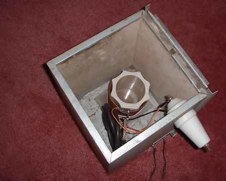
New!
Inside view of 160m LC network (13K .jpg)
4 inch diameter ceramic coil form,
coax capacitor
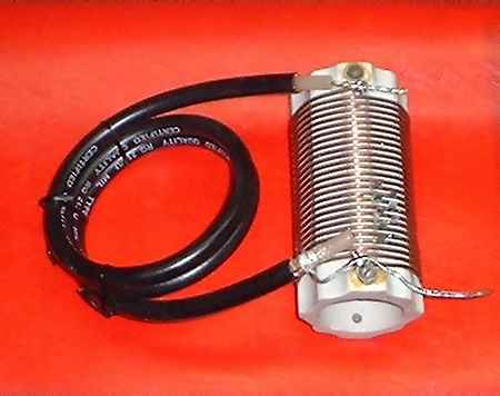
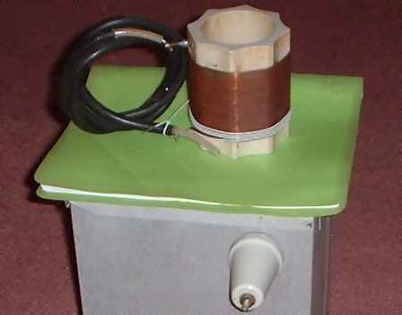
New!
The 160m LC tank (9K .jpg)
30 turns #12 awg, 4 turn link of teflon
insulated wire
Antenna Mounting Both antenna types have a lot of
sag in the horizontal wire. This is probably not of great consequence with the
half square, but is an important mechanical consideration with the bobtail.
When the
vertical conductors are wires, either a 3rd support for the center of the
antenna should be used, or allowance must be made for this sag. My first
bobtail, a 40 meter model, had no center support. Sag was so bad, no matter
how much I tensioned the horizontal wire, that I ended up putting the
support ropes a lot higher.
This made for a funny-looking antenna with the two outer tails about 20 feet
up off the ground, but it did not seem to make any difference in the excellent
performance. The end nulls still appeared to be very deep, and signal reports
within the two main lobes of the antenna were very good. I would be
interested to see the results of computer modeling of this configuration
versus a standard bobtail.
For treeless environments, the vertical elements can be made from
telescoping aluminum tubing just as yagi and other rotary beam
antennas are. W7AV mounts his tubing elements to pressure treated
2 by 4 inch wood bases with U-bolt clamps. The 2 by 4's are set in
ready-mix concrete in 5 gallon plastic buckets. These are fairly heavy,
and are therefore reasonably stable just sitting on the ground (rope
guys are still needed). They can be easily moved around using a
hand truck, garden cart, wheelbarrow, child's wagon, etc.
Note that wood supports at this location might not always be suitable,
as they are also functioning as RF insulators at high voltage points.
They might work fine in dry environments, not as well in wetter
environments. Choosing a longer breakdown path across the 2 by 4
is a good idea. Short pieces of PVC tubing can also
be placed around the metal tubing under the U-bolts,
perhaps even multiple layers, to improve the insulation. Such arrangements
should work fine, although they are not optimum. The best
base insulators are said to be glass or ceramic, chosen so as to minimize
capacitance to ground. If the masts are light enough,
a tall, sturdy glass bottle with thick walls such as a wine bottle
could also serve. The metal tubing should fit loosely around the
neck of the bottle, and should be carefully deburred, beveled, and smoothed
to avoid scoring the glass surface. Large diameter solid fiberglass
rod in sufficient lengths should also perform acceptably,
although it is expensive.
Wind Effects For wire versions of these antennas
mounted on flexible supports like trees, make allowance for movement due to
winds. My 80m half square was mounted between two large oak trees. Near the
top of a tree, the trunk is thinner and more flexible,
and the branches sway more
in the wind. This causes the wire tails to bob up and down. The
distance traveled during high winds is considerable. Smaller branches can
flex a little from mechanical loading by the antenna and reduce this travel,
but my support ropes went over larger, more rigid branches.
After having my tuning
network box repeatedly knocked over or the wire broken off of it,
I learned some methods to protect against this. The best way is to add some
slack in the driven element by running it a short distance horizontally
to the box, and to use an alligator clip as a disconnect.
I like a large clip, which needs a strong tug to pull off. It should be
wiggled occasionally to maintain good electrical contact.
I also chose to mount my box in the center of the ground screen, which was
mounted in turn by short ropes to metal fence posts. The resulting
sag added still more flexibility.
Because of the wind problem, it is actually good to have some sag
in the horizontal wire so that it does not break under tension. Despite seeing
many cautions against using nylon rope for antenna supports, I have used nylon
almost exclusively over the years.
It is true that sunlight eventually destroys nylon
rope, but that process takes many years in my protected, forest environment.
The advantage of nylon rope is that it has a lot of stretch. This is a
good quality that reduces the strain on antenna wires in windy
conditions, making them less likely to break. In time, sunlight
and air pollution make nylon rope less flexible. The only problems I
ever had were ropes parting due to abrasion against trees.
|


