Brushless Operation
Rotor motion is started by generating a revolving magnetic field
in the stator windings which interacts with permanent magnet fields in the
rotor. The revolving field is created by sequentially energizing the winding
phase pairs. The winding phase pairs are energized with current flow in a set
sequence to produce the desired direction of rotation. At any instant, two of
the three phases are energized while the third phase is off. Energizing two
phases simultaneously combines the torque output of both phases and increases
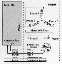
overall torque output. The Model 3912 Encased Control has a pre-wired single
cable terminated (figure 1). This simplifies all commutation and power
connections to stock motors and gearmotors. Chassis style controls and low
voltage controls require separate connections for power leads, commutation, and
(if provided) encoder leads. Motor power leads are equipped with quick
disconnect terminals or terminal blocks for easy control board connection. The
commutation leads from motor and extension cables are terminated with a six-pin,
0.1" center in-line connector which plugs into the commutation terminals on many
Bodine control boards. See figure 2. Stock motors and gearmotors for use with
115 VAC input controls have a circular connector containing phase leads and
commutation connections. The connector on the motor is AMP No. 206044-1, with
No. 66098-7 pins and No. 206070-1 strain relief. The mating connector is AMP No.
206043-3 with No. 66100-7 pins (see figure 1 ). The Motor To Control Connections
table shows a cross reference of lead color code, rectangular commutation
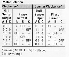
connector, and circular connector pin numbers. Commutation Sequence: The output
truth table for the Hall sensor devices and the corresponding driver outputs
which must be switched +on+ to create phase current flow sequences is shown
below. This sequence causes a Bodine brushless motor/gearmotor to rotate
clockwise. The output shafts of gearmotors with odd number of stages (Bodine
Type designation ending in -D3, -Z3, -W3, -E1, or -E3) will rotate in the
opposite direction. The rotational direction can be changed to counterclockwise
by reversing the phase current flow sequences (6, 5, 4, 3, 2,1). The output
truth table for the Hall sensor devices and the corresponding phase current
output switch must be switched on to create counterclockwise rotation is shown
in the motor rotation table.
Brushless Advantages
Brushless motors provide less maintenance, long life, low EMI,
and quiet operation. They produce more output power per frame size than PM or
shunt wound motors and gearmotors. Low rotor inertia improves acceleration and
deceleration times while shortening operating cycles and their linear
speed/torque characteristics produce predictable speed regulation. With
brushless motors, brush inspection is eliminated making them ideal for limited
access areas and applications where servicing is difficult. Low voltage models
are ideal for battery operation, portable equipment, or medical applications
where shock hazards cannot be tolerated .
Brushless Construction
All Bodine brushless motors have a three-phase four-pole configuration.
Internally, the motor features a wound stator (stationary outer member) and a
permanent magnet rotor. Having the winding in the outer member helps dissipate
winding heat efficiently. Stator windings are connected in a conventional
three-phase wye configuration. The rotor consists of a shaft and a core with
rare earth permanent magnets its circumference providing inherent low inertia.