
undefined
NOTE that this page describes a hobbyist project in which an attempt is made to create an in-circuit debugger for a popular line of microcontroller chips. If you choose to attempt to copy any of the activities described by this author, any risk being taken is strictly yours. I do not promise or guarantee any results for you in any way. If you follow my lead, I hope you enjoy any help or benefit it seems to give you. On the other hand, if such activities wipe out your computer files, somehow empty your bank account, poison your dog, wreck your car, or cause any other problems for you or others, do not blame me because I only allow you to read this for educational purposes. What you do with the information is your business. Naturally, if you use my work as the basis for making something new or different, I would certainly like to see credit given to me for my contributions.
I don't like the taste of C language syntax so I write my PIC18F2550 programs in assembly language. For an assembler, I use GPASM which is part of the GPUTILS utilities. I bought one of the inexpensive K150-style PIC chip programmers and, despite the complaints I have sometimes heard from others, I find that it works pretty well for me. The programmer is designed to install a program into a PIC chip that is plugged into a ZIF socket on the programmer or it can be connected to a PIC system via an ICSP cable and the PIC chip programmed while right in its target system.
In the past, I have had several other ICSP-style programmers and ran into difficulties with using ICSP to store programs into a PIC chip that was in its target system. I soon found myself moving my PIC chips back and forth for each new version of my program that I wished to test between the K150 programmer's ZIF socket and a socket in the target system. With the PIC18F series chips, we have an easy alternative. These PIC chips provide a very simple means to add a USB interface. Microchip has also provided at least one bootloader that can run in the PIC18F chips. The bootloader stores programs for subsequent execution and testing into the same PIC chip in which the bootloader is running.
I quickly found that I prefer to use the bootloader to load new versions of a program that I am developing into my PIC18F2550. If the full extent of my development system were a PC with the GPASM assembler and a target system containing a PIC18F2550 with the USB bootloader, debugging would be pretty difficult sometimes because one cannot directly see what is going on within the program being tested. In the past, I generally resorted to indirect methods to conclude what a program was doing so that I could decide what changes were needed. From past experience, I knew that seeing inside the PIC chip as it does its work would surely help in locating and understanding the sources of problems.
I became interested in having a small in-circuit debugging system that could readily be used in conjunction with a PIC system with the bootloader installed in it. So I began researching what may have already been developed by others.
I found one project developed by Jaromir Sukuba. He reportedly built a handheld device that lets one actually write assembly language code, assemble it, program the result into the PIC chip, and then perform in-circuit debugging with a target system. It featured an LCD display and a 20-pushbutton keyboard. It incorporated its own PIC chip to carry out its work. He did a fine job of photographically documenting his prototypes as his project progressed through 3 different versions but does not actually share with us the code that he wrote nor the schematics of his device. You can explore his pages here: http://jaromir.xf.cz/hdeb/hdeb.html
There is a link on one of his web pages that is intended to access source files for an early version of his device but when I click on that link, my browser warns me that the file is suspicious and should not be downloaded so I skip that. However, one of his pages (http://jaromir.xf.cz/hdeb/bdm/bdm.html) includes some technical details about the PIC's undocumented special internal debugging hardware. That gave me a good start in conceiving how a homemade debugger might be implemented.
The PIC chip's special hardware is the key to the in-circuit debugging capabilities. Normally this special hardware is intended for use in conjunction with Microchip's PICKit systems. Jaromir Sukuba described the basic elements of this special hardware. I continued looking for more information about it. There is not much available that I could find.
I did find that there is a book called "Embedded Design with the PIC18F452 Microcontroller". The book itself is not on line but there is a web page (http://www.microdesignsinc.com/picbook/book_info.html ) with links to downloadable files that are related to the book. A program called QwikBug is intended to be installed into a PIC chip being loaded for testing via a PICKit or other ICSP style PIC programmer. It can then be used to perform debugging operations. The PIC source code for QwikBug can be found here: http://www.microdesignsinc.com/picbook/downloads/asm/QB4520.asm I downloaded that source file and studied some parts of it fairly closely. I have not become an expert on it but I was able to verify much of what Jaromir Sukuba had written.
Appendix A4 for the book mentioned above is downloadable here: http://www.microdesignsinc.com/picbook/bookinfo/CA4.pdf It is essentially a users manual for QwikBug. The last paragraph in that appendix says "This development would not have been possible without the help of Al Lovrich, Greg Robinson, and Craig Miller of Microchip Technology. They supported our understanding of a subset of the BDM features built into the hardware of the chip to support their ICD2 module and needed by QwikBug".
The initial QwikBug project appears to have been done around 2003. Although not widely distributed, the information about the undocumented hardware for supporting in-circuit debugging capabilities in the PIC18F chips has been "out there" for about a decade.
I am sure that there are more capabilities supported by the PIC hardware than Microchip revealed to the QwikBug developers or that Jaromir Sukuba described. I can see at least one place where those additional features are probably to be found. I'll have a bit more about that later.
QwikBug is intended for operation in 40-pin versions of the PIC18F chips, namely PIC18F452 and PIC18F4520. It takes over the use of 4 I/O pins and a UART in those chips. The QwikBug program appears to occupy something over 5,000 bytes of Flash memory. I thought that many of its most important features could be provided in much less memory with careful programming. QwikBug is intended for use with systems in which new versions of a program to be tested are stored into the PIC chip using the ICSP signals.
So I soon had my goal in mind, namely to write a simple in-circuit debugger software package that takes advantage of the undocumented built-in debugging hardware that is present in the PIC18F chips. It needs to provide at least these fundamental features:
Now, after several months of intense effort, (drum roll please) I have arrived at my goal with the creation of "DBg V1.00", a compact in-circuit debugger for the PIC18F2550.
This PIC18F2550 program would probably operate on many other PIC18F series chips as well with only minor modifications. It uses the usual USB connection with a PC to download a new HEX file for testing via the Microchip USB bootloader. Whatever PC program you might use to send a HEX file to your PIC system will still be needed for use in the usual way.
A second connection is needed from the PC to the PIC system. This one is for communicating with DBg. The simplest method of connection is a USB-to-TTL serial converter to transmit a serial signal into the PIC chip and to accept a serial signal from the PIC chip for transmission to the PC. The first USB-to-TTL serial converter that I tried produced 0 and +3.3 volt signals and it did not work until I added a buffer circuit to beef up the signals to 5 volt levels. Suitable USB-to-TTL serial converters that do not require buffering are readily available for low cost (less than $5 including shipping) on eBay and other sources.
NOTE: The RB6 input pin (pin 27) of the PIC18F2550 uses a Schmitt buffer input circuit so it needs signal levels that reach 80% of the supply voltage for a logic 1. Since my PIC18F2550 systems run on +5 volts, that means that when a logic 1 is to be input, the input signal to pin 27 must get up to +4.0 volts (80% of +5.0 volts). This is why the 3.3V signal level from my first USB-to-TTL serial converter was insufficient.
There are several conditions that must be met to enable the built-in debug circuitry of the PIC to operate. Much of it centers around the settings in the PIC chip's CONFIG registers. Perhaps the most obvious is the DEBUG bit. In the PIC18F2550, this is located in bit 7 of Config4L. If the bit is a 1, Debug mode is disabled. If the bit is 0, Debug mode is enabled. Note that it is possible to modify the state of this particular bit to either the 1 or 0 state by executing an appropriate PIC program instruction sequence. It can also be established via a HEX file.
Additionally, the code protection bits for every block of Flash memory must be set to 1 which means the code is not protected. However, there appears to be no restrictions regarding blocks being write protected or protected from reading by other blocks.
Normally, a PIC chip loaded with the bootloader has the code protection turned on for the Flash memory block that contains the bootloader (0x00000 - 0x007FF). Unlike the DEBUG bit mentioned earlier, the code protection for a block of memory cannot be simply turned off by running a PIC program.
Given that the appropriate conditions are met in the PIC chip's configuration settings, there must still be some way that control transfers to the DBg program when certain events occur. For example, when someone presses a reset button to create the reset pulse on the MCLR pin of the PIC, something must cause control to transfer to the debugger instead of just starting up the PIC in the usual way. That something is called the Debug Vector.
The Debug Vector is located in some Flash memory at address 0x200028. When any of the events occurs that should cause a transfer of control to the debugger, the PIC executes whatever instruction is stored at 0x200028, usually a Goto command.
I am not sure if address 0x200028 can be erased and re-programmed by program code in the PIC but, as you will see, it really does not matter.
Short of modifying the bootloader itself, there is apparently no way to have the bootloader load code into a portion of the main Flash memory without first erasing all of Flash except itself. That means that the debugger code cannot remain resident while a new program to be tested is loaded. The further means that the debugger must be loaded right along with the program that is going to be tested. Of course, the debugger can be located in the uppermost portion of Flash while the program to be tested is located in the usual space starting right above the bootloader, at 0x800 on the PIC18F2550. Methods of accomplishing this are presented later.
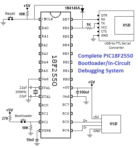
The following schematic shows a minimal PIC18F2550 system capable of running the bootloader and the DBg debugger.
NOTE: While trying to get the debugger to work, I regularly had problems with the debugger appearing to be invoked while the debugger itself was being executed instead of when the intended program to be tested was executing. While searching for a remedy, I tried adding the diode that appears in the schematic and the problem vanished. I must admit that I do not fully understand why it works but it surely does.
The Debug hardware inside PIC18F chips consists of 4 undocumented SFRs. (See the figure below.) The main Debug register is located at address 0xFD4. If you look in the data sheet for any of the PIC18F chips, you will see that 0xFD4 is shown as not-implemented. It is really there, though, just the same. If the prerequisite conditions described above are met and the Debug Vector has been setup with an appropriate Goto command, when any of the triggering events occurs, control will transfer to the address indicated by the Goto command in the Debug Vector and the INBUG bit (bit 7) of the main Debug register will be set to 1.
The INBUG bit is set to 1 whenever the PIC chip has entered the Debug state. During the transition to the Debug state, the address of where the PIC was executing (i.e., the PC) is pushed onto the stack much as it is when a subroutine is called. This is NOT true, however, when the triggering event is Power-On-Reset (POR) or a reset pulse to the /MCLR input pin. When those particular events occur, the stack pointer remains at 0x00 and no return address is pushed onto the stack.
Returning back from the Debug state to the normal state requires execution of the TRet command. This undocumented command (opcode 0x00E1) also clears the INBUG bit, thereby indicating that the PIC chip is no longer in the Debug state.
Bit 6 of the main Debug register is called FRZ (short for Freeze). Suppose a program is to be tested that works with one or more of the PIC chip's timers. It may be desirable for the timers to stop their counting when the program being tested gets interrupted by the debugger. If the FRZ bit is set to a 1, the counting action of the timers stops as long as program execution is in DBg and resumes upon return to the program-under-test. If FRZ is set to 0, the timers can continue counting regardless of whether DBg is in control or not.
Bit 5 of the main Debug register is the SSTP bit (short for Single Step). If the SSTP bit is set when control returns from DBg to the program-under-test, one program instruction will be executed and then control will again enter DBg. That is, only a single step of the program being tested will get to be executed. If the SSTP bit is 0 when control returns from DBg to the program-under-test, execution will be permitted to progress normally until some other event interrupts it.
We will skip bit 4 for now and come back to it in a moment. Bits 5, 6, 7, and 8 are associated with the use of the two I/O pins of the PIC chip that normally relate to RB6 and RB7. These 2 pins also happen to be the 2 pins used for ICSP programming. Even though we are not using ICSP programming in this situation, there are reasons those 2 pins are used for both programming and debugging functions.
In normal operation, the RB6 and RB7 pins are associated with bits 6 and 7 of PortB. Whether each is moded for input or output use is controlled by bits 6 and 7 of TrisB. In Debug mode, their modes (input versus output) are controlled by TSB6 and TSB7 in bits 0 and 1 of the main Debug register. If either is moded to be an input, the state of the pin can be read on the appropriate B6 or B7 bit in bits 2 or 3 of the main Debug register. If either is moded to be an output, the state of the pin can be controlled by setting or clearing the appropriate B6 or B7 bit.
There is a special feature related to the RB6 pin when in the hardware Debug mode. If the PIC chip is executing code in the program-under-test (that is, not in DBg), the INBUG bit of the main Debug register will be off. Under those conditions, if the RB6 pin makes a high-to-low transition, that constitutes one of the special events that can trigger the transfer of control from the program-under-test to DBg. As a result, DBg always has RB6 set to be an input and RB7 is set to be an output.
Bit 4 of the main Debug register is the SHDW (short for Shadow) bit. If the SHDW bit is set to 1, the 3 Breakpoint registers are made accessible to the DBg program. If the SHDW bit is 0, they cannot be accessed. In some PIC18 series chips, the addresses of all 3 of the Breakpoint registers are shown as unimplemented in the data sheet. In fact, for the PIC18F2550, which I use, only address 0xFB9 is shown as unimplemented, initially leading me to think that the Breakpoint registers must be located at some other addresses. Testing of all other possible so-called "unimplemented" addresses proved they were not in any of those locations. Then I realized that when the SHDW bit is set to 1, the SFRs that are normally located at 0xFB7 and 0xFB8 become inaccessible at those addresses and the associated Breakpoint registers appear in their place.
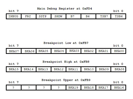
Concerning the Breakpoint registers, taken together they contain a 20-bit address value. If the SHDW bit of the main Debug register is set to 1 (which makes the Breakpoint registers accessible) and the PIC chip's program counter reaches a count that matches the address in the Breakpoint register, it is considered a breakpoint match. This is also an event that can trigger the transfer of control from the program-under-test to DBg.
PIC chip program instructions are always located at even addresses in Flash memory. Therefore, the least significant bit of the PC (Program Counter) is always permanently fixed at 0. Consequently, the address stored in the Breakpoint registers does not need to hold the true address of the breakpoint. Instead, the Breakpoint registers hold the breakpoint address divided by 2.
Notice the 4 most significant bits in the Breakpoint Upper register, those shown with question marks (?). According to both Jaromir Sukuba and the program comments in QwikBug, it is important that these bits not be altered during the setting of the Breakpoint registers. These bits probably relate to additional features of the Debug hardware in the PIC18 chips but their purpose is not known. The PIC chip Debug hardware is likely to also support features such as the setting of multiple breakpoints as well as the monitoring of RAM or SFR addresses to detect when one is written or when its contents become a specified value as these are features commonly provided by in-circuit debuggers in general. The reader is invited to explore these mysteries, determine their purposes, and build additional DBg features based on them.
Before your own program (that you wish to test) is loaded along with DBg into your PIC system, the PIC chip must be set up for debugging activity. In general, the requirements for the PIC system include:
The bootloader must be installed in the PIC18 series chip in the so-called "boot block" which ranges in Flash from 0x00000 to 0x007FF. While the standard Reset Vector is located at 0x00000, the alternate version of it must be at 0x00800. That is, your program will need to have a starting address of 0x00800 which is typical for programs installed by the bootloader.
I have long used a USB bootloader in the PIC18F2550 chips. Its source code is written in C code but I do not use C. I also have the HEX file for the bootloader and that was all I really needed.
The configuration registers of the PIC chip must be set up such that no Flash memory blocks are code-protected, not even the boot block in which the bootloader resides. (It is ok for the boot block to be write protected so that no executing program can alter it.) Also, the DEBUG bit in the appropriate configuration register must be set up for Debug mode. In the PIC18F2550 which I use, the DEBUG bit is bit 7 of Config4L and it must be 0 to enable Debug mode.
The bootloader HEX file with which I started has configuration settings in it that include the boot block being code protected and the DEBUG bit set to 1. That meant I had to do something about these settings. The solution was pretty easy, even without using the C language source code. I wrote a very straightforward assembly language source file whose only purpose was to establish the appropriate settings for the configuration registers. I knew the HEX file for the bootloader was intended for a system with a 20 MHz crystal and which used the internal PLL circuitry to establish the typical 48 MHz clock in the PIC so I arranged my configuration settings in that same way. I also selected that the DEBUG bit be set up for Debug mode operation and set all the code protection settings to disable code protection. I did set the write protection to ON for the boot block to help protect the bootloader from being scrambled. You can see the assembly language source code that I used to establish the configuration settings in the section on this page entitled PIC18F2550 Assembly Language Source Code To Establish Configuration.
When I assembled the source file, it produced this small HEX file:
:020000040000FA
:020000040030CA
:0E000000240E381EFF8000FF0FC00FA00F401F
:00000001FF
The 1st line appears at the front of all HEX files and indicates (via the 040000 in it) that if data bytes follow, they should be stored in the first 64 kilobytes of address space. However, in this case, there are no such data bytes following it. Instead, the 2nd line indicates (by way of the 040030 in it) that data bytes following it are to be stored in the configuration registers. Indeed, the data contained in the 3rd line consists of all the configuration register settings in a single HEX format line. The 4th line appears at the end of every HEX file and simply marks the end of the file. Therefore, what matters most in this small file for our purposes are the 2nd and 3rd lines.
Now have a look at the last few lines of the HEX file for the bootloader. Note the lines that are highlighted. The 1st of the highlighted lines is just like the 2nd line in the small HEX file above. As before, it signals that the data bytes that follow are settings for the configuration registers. In this case, however, instead of all the settings appearing on a single line as they do in the listing above, they are spread out over some 8 different lines. Just as with the previous file, you can see the same line at the very end marking the end of the HEX file. I could have used any simple text editor. In my case, I chose WordPad. I replaced these highlighted lines with a copy of the 2nd and 3rd lines from the first HEX file and saved the result as a new HEX file to be used to program my PIC chip with the USB bootloader and appropriate Debug mode configuration settings.
.
.
.
:0C075000FCD7F350E9601200EE6AFCD701
:04075C0013EE00F0A8
:1007600023EE00F0F86A059C00EC03F0BCEC03F00B
:080770004FEC03F0FBD712006F
:0207780012006D
:020000040030CA
:0100000024DB
:010001000EF0
:0100020038C5
:010003001EDE
:01000500807A
:010006008079
:010009008076
:01000B00A054
:00000001FF
In the resultant HEX file, the end of the file now looked like this:
.
.
.
:0C075000FCD7F350E9601200EE6AFCD701
:04075C0013EE00F0A8
:1007600023EE00F0F86A059C00EC03F0BCEC03F00B
:080770004FEC03F0FBD712006F
:0207780012006D
:020000040030CA
:0E000000240E381EFF8000FF0FC00FA00F401F
:00000001FF
The Debug Vector is located at Flash address 0x200028 and must be written with a Goto command to transfer control to the address assigned to the label DBgEntry. My intent is to place DBgEntry at the very top of the available program code Flash memory. In the PIC18F2550, for example, the highest Flash address available for program code is 0x007FFF. The Goto command stored at DBgEntry takes 4 bytes so it occupies 0x007FFC to 0x007FFF. The rest of DBg is stored just below the DBgEntry location.
I discovered that the Microbrn.exe software that drives the K150-style PIC programmer has an option built into it that dramatically simplifies this. Just click on Programmer, then Debug Vector, and then Write. It then prompts for the address to serve as the target of the Goto command. In my case, I entered 7FFC and clicked OK. The Goto command was then automatically programmed into the Debug Vector of the PIC chip that I had inserted into the programmer.
Ideally, the RB6 and RB7 I/O pins would be connected to no other electronic components other than those shown in the schematic above. In reality, I have each of these I/O pins also connected to a 1K resistor to a blue LED to ground. Blue and white LEDs have a higher forward voltage drop than do LEDs of most other colors. As a result, they do not attenuate the I/O signals very much at all and still serve as bright indicators.
Whenever I finish developing a new program (with the aid of DBg to debug it), the DEBUG bit in the configuration registers is set to 1 to turn off Debug mode. Then the USB-to-TTL converter module is removed along with the associated resistor and diode. The same blue LEDs remain in place to serve as useful indicators in the finished system. Note however that while DBg is in use, the blue LEDs do not indicate any signals intended for them by the program under development. The blue LEDs turned out to be so bright that, in retrospect, resistors of perhaps 4.7K might have been a better choice than 1K as the loading on the I/O pins would have been even less.
The DBg program relies on bit-bang I/O techniques to perform its serial communication with the PC. That means it does not use any type of hardware UART to perform the serial-to-parallel or parallel-to-serial conversions involved in receiving and sending ASCII characters via the serial interface. The communication speed is determined strictly by program timing. That is, program delays created by counting are the basis for the serial communications timing.
If one knows the serial communication baud rate to be used by the PC as well as the clock speed of the PIC system, setting these values into a couple of symbols in the DBg source file will result in DBg knowing how to receive and transmit serial data with the proper timing. However, if one does not know the required baud rate or does not know the PIC system's clock speed, substituting 0 for the baud rate or 0 for the clock speed will cause DBg to resort to an Auto-Baud technique to establish the communication timing.
Here is how Auto-Baud works. When a program is to be tested using DBg, the program and DBg are both loaded into the PIC system per usual. However, when the Reset button is pressed and DBg assumes control, it does not send anything to the PC. Instead, it waits on the operator to press a key on the PC's keyboard. The operator should press the Enter key. The DBg program detects the resulting Carriage Return character being sent to the PIC system and measures the serial communication speed relative to the clock speed of the PIC system. That provides enough information for DBg to perform its communication activities with proper timing. After that point, the usage of DBg is exactly the same as it would be if the baud rate and clock speed were known until the operator recycles power or again presses the Reset button.
Following a Power-On-Reset or a press of the Reset button, DBg needs to know if the bootloader is going to be running or if the program-under-test is going to be starting up. The bootloader itself decides this by testing an input bit. For example, in the bootloader that I use, the RC2 I/O pin is sampled. If it is 1, the bootloader should run. If it is 0, the program-under-test should run.
In order that DBg can recognize the same condition, DBg needs to be fitted with an instruction for detecting whether the bootloader will be run or the program-under-test will run. Near the start of the DBg source file, there is a symbol defined to contain a single instruction. The symbol is called DBgSkNtBl, which is short for Skip If Not To Run The Bootloader. In my system, I have this symbol defined like this:
#Define DBgSkNtBl btfsc PortC,2
If a bootloader is used that uses the opposite sense or if a different I/O bit is sensed, this Define statement will need adjustment before assembling the DBg source file.
Since the bootloader occupies the block of Flash memory that includes the Reset Vector, your own programs must be written to start at a different address that is located somewhere after the bootloader. Typically, this Alternate Reset Vector is at 0x08000. The address of the Alternate Reset Vector is set into the symbol DBgAlRsVc near to the top of the DBg source file.
There are two ways to set up DBg for testing your own program. The first is to combine the HEX file from your own program with the HEX file created by assembling DBg. The second method is to combine the source code for DBg with your own source code and assemble them together which results in a single HEX file containing both the program to be tested and DBg.
In this method, you take these steps:
In this method, you take these steps:
The details of how you set up the terminal emulator will vary from one to another but there are certain settings that must be correct.
The Com port setting chosen for the terminal emulator must match that assigned to the USB-to-TTL serial converter. If you are using Microsoft Windows, look in the Haardware Device Manager to view the Com port number assigned to your USB-to-TTL serial converter. If necessary, the Com port number can be changed there as well as some terminal emulators are limited on which Com port numbers may be selected for their use.
If you are running DBg that has been built for a specific serial baud rate, the serial port used by the terminal emulator must be set for that same baud rate. If DBg has been built for Auto-Baud use, then nearly any baud rate will probably work. I generally use 9600 baud but I run my PIC18F2550 chips with a 48 MHz clock. A very low clock speed might need you to select a lower baud rate to work well.
Other settings for the serial communications should be:
When DBg first receives control, it identifies itself and then sends its output line to the terminal emulator running in the PC to describe the current state of the PIC system. Here is an example of what it looks like:
DBg V1.00
P:00820 W:07 S:05 F:1 A:000=V:00 B:FFFFE >
The identification line appears only once when Power-On-Reset or a press of the Reset button occurs and the bootloader is not used. Note that if Auto-Baud is in use, the operator must press Enter before the identification line is displayed.
The next line is DBg's main output line. Every time DBg outputs, it is in this format. All numbers in the line are in hexadecimal format. The various parts of the line describe different aspects of the system as follows:
P:00820 This tells us that when execution of the program-under-test stopped, the PC contained 00820. That is, if continued, the next instruction will be executed at the address shown.W:07 This tells us the current contents of the W register in the program-under-test.S:05 This tells us the current contents of the Status register in the program-under-test.F:1 This tells us the current state of the Freeze option. If the Freeze setting is 1, any counting action of the PIC's timers is frozen (stopped) as long as DBg itself is executing but is allowed to continue whenever control returns to the program-under-test. If the Freeze setting is 0, the PIC's timers are permitted to continue to count all the time.A:000 This tells us the RAM/SFR address whose value is being displayed after V:V:00 This tells us the current value in the RAM/SFR address shown after the A:.B:FFFFE This tells us the current breakpoint addresss setting.> This is the prompt that indicates that DBg is ready to accept one of its commands.DBg accepts several commands. Each command begins with a command letter and many are followed by a numeric value terminated with the Enter key. If the operator types a character that is not accepted as a command, DBg responds with a question mark (?) and then again displays its output line and waits for another command.
NOTE - On a few occasions when a program under test has run off the rails and just gotten totally lost and crashed, I have found that my PIC system did not want to recover properly by simply pressing the reset button. In those few instances, a simple procedure that has never failed to regain control was to interrupt power to the PIC system and then restore the power while the reset button was being held down. Subsequent release of the reset button permitted the system to operate as expected once more.
If you know much about bootloaders, find this interesting, and are looking for a challenge, I have a project laid out for you that would result in a much neater setup.
The Bootloader/Debugger Challenge
:020000040000FA
:107D00000000FED7E0CFF5F70701EF91F2BEEF815B
:107D1000E8CFF3F7D8CFF4F7EACFF7F7E9CFF6F7E4
:107D2000FBCFF9F7FACFF8F7FC6623D0FC2AFF6AFD
:107D3000FE6AFD6AD90ED46E000EB76E040EB86EE0
:107D4000F00EB916EF9582B4D498D49AE862D48A2A
:107D5000F8C7FAFFF9C7FBFFF6C7E9FFF7C7EAFF65
:107D6000F4C7D8FFF3C7E8FFEFB1F28EF5C7E0FF25
:107D7000E100D4A8EAD7E86AE82CFED7EFB51CD01A
:107D8000EF85B768B868070EB912B996FA6BFB6B46
:107D900010D90FD9440ED8D8420ED6D8670ED4D8F1
:107DA000200ED2D8560ED0D8310ECED82E0ECCD82A
:107DB000300ECAD8300EC8D8FCD8500EF7D8FF50B5
:107DC000BED8FE50B8D8FD50EED8570EEFD8F351BC
:107DD000EAD8530EEBD8F451E6D8460EE7D8E86A55
:107DE000D4BC010EACD8E0D8410EE0D8FB51A7D8E6
:107DF000FA51A1D83D0EA8D8560ED8D8FAC7E9FF37
:107E0000FBC7EAFFEF50CFD8420ED0D8D890B73496
:107E1000FC6FB834FD6FB93492D8FD518CD8FC5149
:107E2000C2D83E0E91D89ED8E00FD8B81BD0F051E2
:107E30008BD8F051B90FD8B488D7F90FD8B487D7F9
:107E40000D0F36E0F10F1FE0FA0F43E0FF0F0DE0DA
:107E5000040F12E0110F20E0FC0F46E01B0F33E08F
:107E6000FE0F34E03F0E70D8A7D740D8FD11FE11A9
:107E7000F9E1FCC7F3F7A0D739D8FD11FE11F2E103
:107E8000FCC7F4F799D732D8EDE1FC51FD6EFD51F6
:107E9000FE6EFE51FF6E90D729D8E4E1F00EB916C0
:107EA000FE310F0BB912FD31B86EFC31B76E84D7BD
:107EB0001DD8FE11D7E1FD51F00BD4E1FCC7FAF754
:107EC000FDC7FBF779D7FA4BFB2B76D7FA07FB5B9D
:107ED00073D70CD8FD11FE11C5E1FAC7E9FFFBC746
:107EE000EAFFFCC7EFFF68D7D47C66D75DD8FC6B90
:107EF000FD6BFE6BEF9336D8B90F18E7060F02E65D
:107F00000A0F04D0070F12E70A0F10E6F26FEF8393
:107F1000F0511AD8040EF16FD890FC37FD37FE37B8
:107F2000FE99F12FF9D7F251FC13E5D7F051EFA3E9
:107F3000E86AF30F1200F26FE83801D8F2510F0B24
:107F4000F60FD8A8070F3A0FFF6F0A0EF16FD890FF
:107F5000D486D8A0D4961ED81DD8D880FF33F12F50
:107F6000F7D71200D4B4FED715D8080EF16F12D887
:107F700011D8D890D4B4D880F033F12FF8D7F0517D
:107F80009F0FD8B805D0E60FD8B8E00F7B0FF06F81
:107F9000F05112009A0EED6F000EEE6FE86AED07D9
:107FA000EE5BFDE21200C7DF200ECED7CDDF3A0E2A
:0A7FB000CBD70D0EC9DF0A0EC7D7AC
:047FFC0082EF3EF0E2
:00000001FF
:020000040000FA
:107D00000000FED7E0CFF5F70701EF91F2BEEF815B
:107D1000E8CFF3F7D8CFF4F7EACFF7F7E9CFF6F7E4
:107D2000FBCFF9F7FACFF8F7FC6623D0FC2AFF6AFD
:107D3000FE6AFD6AD90ED46E000EB76E040EB86EE0
:107D4000F00EB916EF9582B4D498D49AE862D48A2A
:107D5000F8C7FAFFF9C7FBFFF6C7E9FFF7C7EAFF65
:107D6000F4C7D8FFF3C7E8FFEFB1F28EF5C7E0FF25
:107D7000E100D4A8EAD7E86AE82CFED7EFB51CD01A
:107D8000EF85B768B868070EB912B996FA6BFB6B46
:107D900010D90FD9440ED8D8420ED6D8670ED4D8F1
:107DA000200ED2D8560ED0D8310ECED82E0ECCD82A
:107DB000300ECAD8300EC8D8FCD8500EF7D8FF50B5
:107DC000BED8FE50B8D8FD50EED8570EEFD8F351BC
:107DD000EAD8530EEBD8F451E6D8460EE7D8E86A55
:107DE000D4BC010EACD8E0D8410EE0D8FB51A7D8E6
:107DF000FA51A1D83D0EA8D8560ED8D8FAC7E9FF37
:107E0000FBC7EAFFEF50CFD8420ED0D8D890B73496
:107E1000FC6FB834FD6FB93492D8FD518CD8FC5149
:107E2000C2D83E0E91D89ED8E00FD8B81BD0F051E2
:107E30008BD8F051B90FD8B488D7F90FD8B487D7F9
:107E40000D0F36E0F10F1FE0FA0F43E0FF0F0DE0DA
:107E5000040F12E0110F20E0FC0F46E01B0F33E08F
:107E6000FE0F34E03F0E70D8A7D740D8FD11FE11A9
:107E7000F9E1FCC7F3F7A0D739D8FD11FE11F2E103
:107E8000FCC7F4F799D732D8EDE1FC51FD6EFD51F6
:107E9000FE6EFE51FF6E90D729D8E4E1F00EB916C0
:107EA000FE310F0BB912FD31B86EFC31B76E84D7BD
:107EB0001DD8FE11D7E1FD51F00BD4E1FCC7FAF754
:107EC000FDC7FBF779D7FA4BFB2B76D7FA07FB5B9D
:107ED00073D70CD8FD11FE11C5E1FAC7E9FFFBC746
:107EE000EAFFFCC7EFFF68D7D47C66D75DD8FC6B90
:107EF000FD6BFE6BEF9336D8B90F18E7060F02E65D
:107F00000A0F04D0070F12E70A0F10E6F26FEF8393
:107F1000F0511AD8040EF16FD890FC37FD37FE37B8
:107F2000FE99F12FF9D7F251FC13E5D7F051EFA3E9
:107F3000E86AF30F1200F26FE83801D8F2510F0B24
:107F4000F60FD8A8070F3A0FFF6F0A0EF16FD890FF
:107F5000D486D8A0D4961ED81DD8D880FF33F12F50
:107F6000F7D71200D4B4FED715D8080EF16F12D887
:107F700011D8D890D4B4D880F033F12FF8D7F0517D
:107F80009F0FD8B805D0E60FD8B8E00F7B0FF06F81
:107F9000F0511200E00EED6F040EEE6FE86AED078F
:107FA000EE5BFDE21200C7DF200ECED7CDDF3A0E2A
:0A7FB000CBD70D0EC9DF0A0EC7D7AC
:047FFC0082EF3EF0E2
:00000001FF
:020000040000FA
:107D00000000FED7E0CFF5F70701EF91F2BEEF815B
:107D1000E8CFF3F7D8CFF4F7EACFF7F7E9CFF6F7E4
:107D2000FBCFF9F7FACFF8F7FC6623D0FC2AFF6AFD
:107D3000FE6AFD6AD90ED46E000EB76E040EB86EE0
:107D4000F00EB916EF9582B4D498D49AE862D48A2A
:107D5000F8C7FAFFF9C7FBFFF6C7E9FFF7C7EAFF65
:107D6000F4C7D8FFF3C7E8FFEFB1F28EF5C7E0FF25
:107D7000E100D4A8EAD7E86AE82CFED7EFB527D00F
:107D8000FE0EEB6FEC69D4B4FED77AD8D4A4FDD73D
:107D900077D8D4B4FDD7EF85B768B868070EB912A5
:107DA000B996FA6BFB6B17D916D9440EDFD8420E81
:107DB000DDD8670EDBD8200ED9D8560ED7D8310EB5
:107DC000D5D82E0ED3D8300ED1D8300ECFD803D977
:107DD000500EFED8FF50C5D8FE50BFD8FD50F5D884
:107DE000570EF6D8F351F1D8530EF2D8F451EDD81E
:107DF000460EEED8E86AD4BC010EB3D8E7D8410EDF
:107E0000E7D8FB51AED8FA51A8D83D0EAFD8560EE0
:107E1000DFD8FAC7E9FFFBC7EAFFEF50D6D8420E1A
:107E2000D7D8D890B734FC6FB834FD6FB93499D82F
:107E3000FD5193D8FC51C9D83E0E98D8A5D8E00F73
:107E4000D8B81BD0F05192D8F051B90FD8B47DD723
:107E5000F90FD8B47CD70D0F3DE0F10F26E0FA0FF3
:107E60004AE0FF0F14E0040F19E0110F27E0FC0FA8
:107E70004DE01B0F3AE0FE0F3BE03F0E77D8A7D74F
:107E800000D000D000D0E86AEB2BEC23120040D8E1
:107E9000FD11FE11F2E1FCC7F3F799D739D8FD11B6
:107EA000FE11EBE1FCC7F4F792D732D8E6E1FC51C2
:107EB000FD6EFD51FE6EFE51FF6E89D729D8DDE1C2
:107EC000F00EB916FE310F0BB912FD31B86EFC3150
:107ED000B76E7DD71DD8FE11D0E1FD51F00BCDE17D
:107EE000FCC7FAF7FDC7FBF772D7FA4BFB2B6FD72E
:107EF000FA07FB5B6CD70CD8FD11FE11BEE1FAC787
:107F0000E9FFFBC7EAFFFCC7EFFF61D7D47C5FD76F
:107F10005DD8FC6BFD6BFE6BEF9336D8B90F18E79D
:107F2000060F02E60A0F04D0070F12E70A0F10E649
:107F3000F26FEF83F0511AD8040EF16FD890FC372E
:107F4000FD37FE37FE99F12FF9D7F251FC13E5D733
:107F5000F051EFA3E86AF30F1200F26FE83801D88E
:107F6000F2510F0BF60FD8A8070F3A0FFF6F0A0E4A
:107F7000F16FD890D486D8A0D4961ED81DD8D880BA
:107F8000FF33F12FF7D71200D4B4FED715D8080E5F
:107F9000F16F12D811D8D890D4B4D880F033F12F23
:107FA000F8D7F0519F0FD8B805D0E60FD8B8E00F3A
:107FB0007B0FF06FF0511200EBC7EDF7ECC7EEF757
:107FC000E86AED07EE5BFDE21200C7DF200ECED7B8
:0E7FD000CDDF3A0ECBD70D0EC9DF0A0EC7D794
:047FFC0082EF3EF0E2
:00000001FF
DBgBnk is the number of the memory bank where you would like DBg to store its own variables. By keeping it up high while keeping your own variables down low in memory they do not conflict. DBg's variables will be placed in the very top of whichever bank is selected. In a PIC18F2550, the number of the highest available bank of RAM is 7. If the program-under-test will be using the PIC's USB facilities, banks 4, 5, 6, and 7 are reserved for USB operations. In this case, set DBgBnk to 3.
DBgClkFrq is the PIC's clock frequency. This is often different from the frequency of a crystal that is used with the PIC chip. For most systems using a 20 MHz crystal, an internal PLL (Phase Locked Loop) is used to multiply the resulting clock frequency to 48 MHz. Then circuitry in the PIC chip derives 4 clock phases from that, resulting in 12 million instruction times per second execution speed. In this scenario, the clock speed is 48 MHz and DBgClk should be set equal to 48000000 (decimal). As explained earlier in Known Baud Rate & Clock Speed Versus Auto-Baud, if the clock speed is unknown, you can just set DBgClk to 0 and the Auto-Baud feature will be enabled.
DBgBaudRt is the baud rate that used to send and receive characters via the serial link. If you are running a terminal emulator in a PC, it should be easy to determine what the baud rate setting is for the serial line you are using. Just set the DBgBaudRt symbol equal to the baud rate. For example, if your serial line is to be operated at 9600 baud, set DBgBaudRt to 9600 (decimal). If you do not know the baud rate or if you wish to enable Auto-Baud for any other reason, you can set DBgBaudRt to 0.
;DBgCfg.asm
;PIC 18F2550 source file to establish configuration suitable for
;bootloader to be used with Debug mode. (20 MHz crystal, 48 MHz clock)
;
          LIST p=18F2550, r=DEC
          Include   <p18F2550.inc>

;Settings for Config1 (H/L)
Config    PLLDIV  = 5         ;Divide by 5 (20 MHz oscillator input)
Config    CPUDIV  = OSC1_PLL2 ;[Primary Oscillator Src: /1][96 MHz PLL Src: /2]
Config    USBDIV  = 2         ;USB clock source comes from the 96 MHz PLL divided by 2
Config    FOSC    = HSPLL_HS  ;HS oscillator, PLL enabled (HSPLL)
Config    FCMEN   = OFF       ;Fail-Safe Clock Monitor disabled
Config    IESO    = OFF       ;Oscillator Switchover mode disabled

;Settings for Config2 (H/L)
Config    PWRT    = ON        ;PWRT enabled
Config    BOR     = OFF       ;Brown-out Reset disabled in hardware and software
Config    BORV    = 3         ;Minimum setting
Config    VREGEN  = ON        ;USB voltage regulator enabled
Config    WDT     = OFF       ;WDT disabled (control is placed on the SWDTEN bit)
Config    WDTPS   = 32768     ;1:32768

;Settings for Config3 (H)
Config    CCP2MX  = OFF       ;CCP2 input/output is multiplexed with RB3
Config    PBADEN  = OFF       ;PORTB<4:0> pins are configured as digital I/O on Reset
Config    LPT1OSC = OFF       ;Timer1 configured for higher power operation
Config    MCLRE   = ON        ;MCLR pin enabled; RE3 input pin disabled

;Settings for Config4 (L)
Config    STVREN  = OFF       ;Stack full/underflow will not cause Reset
Config    LVP     = OFF       ;Single-Supply ICSP disabled
Config    XINST   = OFF       ;Instr. set extension & Indexed Addressing mode disabled (Legacy mode)
Config    DEBUG   = ON        ;Background debugger enabled, RB6 & RB7 dedicated to In-Circuit Debug

;Settings for Config5 (H/L)
Config    CP0     = OFF       ;Block 0 0800-1FFF is not code-protected
Config    CP1     = OFF       ;Block 1 2000-3FFF is not code-protected
Config    CP2     = OFF       ;Block 2 4000-5FFF is not code-protected
Config    CP3     = OFF       ;Block 3 6000-7FFF is not code-protected
Config    CPB     = OFF       ;Boot block 0000-07FF is not code-protected
Config    CPD     = OFF       ;Data EEPROM is not code-protected

;Settings for Config6 (H/L)
Config    WRT0    = OFF       ;Block 0 0800-1FFF is not write-protected
Config    WRT1    = OFF       ;Block 1 2000-3FFF is not write-protected
Config    WRT2    = OFF       ;Block 2 4000-5FFF is not write-protected
Config    WRT3    = OFF       ;Block 3 6000-7FFF is not write-protected
Config    WRTC    = OFF       ;Configuration registers 300000-3000FF are not write-protected
Config    WRTB    = ON        ;Boot block 0000-07FF is  write-protected
Config    WRTD    = OFF       ;Data EEPROM is not write-protected

;Settings for Config7 (H/L)
Config    EBTR0   = OFF       ;Block 0 0800-1FFF not protected from table reads executed in other blks
Config    EBTR1   = OFF       ;Block 1 2000-3FFF not protected from table reads executed in other blks
Config    EBTR2   = OFF       ;Block 2 4000-5FFF not protected from table reads executed in other blks
Config    EBTR3   = OFF       ;Block 3 6000-7FFF not protected from table reads executed in other blks
Config    EBTRB   = OFF       ;Boot block 0000-7FF not protected from table reads executed in other blks

          END
List p=18F2550, r=dec
#Include <p18f2550.inc>
; *************************************************
; * DBg *
; * *
; * A simple in-circuit PIC18F debugger that runs *
; * in conjunction with the Microchip bootloader. *
; * *
; * Author: Joe Watson *
; * Date: 2014-09-02 *
; * Notice: Released to the public domain *
; * *
; *************************************************
;
;
;------------------------------------------------------------------------------------------
; Below are some settings you might want/need to establish for your particular system.
;------------------------------------------------------------------------------------------
DBgBnk equ 3 ;Highest bank on PIC18F2550 is 7. If using USB, then
;substitute 3.
;
DBgClkFrq equ 48000000 ;Clock frequency, not crystal frequency.
;For example, 20MHz crystal is often scaled up to 48MHz
;using PLL inside the PIC. In that case, use 48000000.
;If the clock frequency is unknown, set DBgClkFrq equ 0 to
;to trigger the use of the auto-baud feature.
;
DBgBaudRt equ 9600 ;Put in the baud rate at which you want the serial line to
;operate. For example DBgBaudRt equ 9600 means the DBg
;program should send and receive at 9600 baud. You can
;use 0 here for the baud rate if you want to enable the
;auto-baud feature.
;
;This debugger is intended for use with PIC18F chips which
;are running with a bootloader. The author uses a Microchip
;bootloader that determines whether it should run or not
;based on the state of an input pin, namely RC2. In his
;system, if RC2 is a 1 when the system is reset, the
;bootloader should run. If it is a 0, the bootloader should
;not run and the existing user app should run, starting at
;address 0x0800. To allow for the use of bootloaders that
;might sense a different input pin or use the opposite bit
;sense, here we define a command that will skip if the
;bootloader is NOT suppose to be started.
#Define DbgSkNtBl btfsc PortC,2,A ;Skip if not to start the bootloader.
;
DBgAlRsVc equ 0x0800 ;This defines the alternate Reset Vector. That is, it is where
;user code execution normally commences if the bootloader is
;to be skipped.
;------------------------------------------------------------------------------------------
;Definitions and settings
;------------------------------------------------------------------------------------------
If DBgClkFrq != 0 && DBgBaudRt != 0
DBgHfBtCt equ DbgClkFrq/DBgBaudRt/32 ;Count needed to cause DBgHalfBt sub to delay a
;half bit time for serial communications.
Else
DBgHfBtCt equ 0 ;Zero triggers use of auto-baud feature.
EndIf
DbgReg equ 0xFD4 ;Main Debug mode register. This SFR is actually always
;present if the Debug bit is set in the config registers
;despite the data sheet showing the address as having none.
DBgBkPtL equ 0xFB7 ;These 3 breakpoint SFRs are accessible only when
DBgBkPtH equ 0xFB8 ;the DBgShadow bit of the debug register is set to 1.
DBgBkPtU equ 0xFB9 ;NOTE: Must not alter any of the top 4 bits of DBgBkPtU.
;They are set with the breakpoint address (divided by 2)
;when a breakpoint is set. The breakpoint can be rendered
;ineffective by either setting the DBgShadow bit of DBgReg
;to 0 or by setting the breakpoint address to an address
;will never be reached such as 0xFFFFE.
DBgBkPt equ DBgBkPtL ;Lets us talk about them as a multibyte variable.
#Define DBgFrz DBgReg,6 ;Stops PIC timers during debugger execution when set.
#Define DBgSglStp DBgReg,5 ;Debugger restarts after 1 user instruction when set.
#Define DBgShadow DBgReg,4 ;Makes breakpoint registers accessible when set.
#Define DBgB7 DBgReg,3 ;Equivalent to PortB,7 when in debug mode.
#Define DBgB6 DBgReg,2 ;Equivalent to PortB,6 when in debug mode.
#Define DBgTSB7 DBgReg,1 ;Equivalent to TrisB,7 when in debug mode.
#Define DBgTSB6 DBgReg,0 ;Equivalent to TrisB,6 when in debug mode.
#Define tret DW 0x00E1 ;Undocumented opcode to return control from debugger.
;It switches the PIC from debugger mode back to user
;code mode.
#Define DBgCR 0x0D ;Carriage Return character
#Define DBgLF 0x0A ;Line Feed character
If DBgHfBtCt == 0
;These two bytes are needed only if the auto-baud feature is to be used.
DBgBaudL equ DBgBnk*0x100+0xEB
DBgBaudH equ DBgBnk*0x100+0xEC
EndIf
DBgCntL equ DBgBnk*0x100+0xED
DBgCntH equ DBgBnk*0x100+0xEE
DbgFlgs equ DBgBnk*0x100+0xEF
DbgChar equ DBgBnk*0x100+0xF0
DbgCntr equ DBgBnk*0x100+0xF1
DbgTmp equ DBgBnk*0x100+0xF2
DBgW equ DBgBnk*0x100+0xF3
DBgStatus equ DBgBnk*0x100+0xF4
DBgBSR equ DBgBnk*0x100+0xF5
DBgFSR0L equ DBgBnk*0x100+0xF6
DBgFSR0H equ DBgBnk*0x100+0xF7
DBgPCLatH equ DBgBnk*0x100+0xF8
DBgPCLatU equ DBgBnk*0x100+0xF9
DBgVarAdL equ DBgBnk*0x100+0xFA
DBgVarAdH equ DBgBnk*0x100+0xFB
DbgNbrL equ DBgBnk*0x100+0xFC
DbgNbrH equ DBgBnk*0x100+0xFD
DbgNbrU equ DBgBnk*0x100+0xFE
DbgOutChr equ DBgBnk*0x100+0xFF
DBgCnt equ DBgCntL ;Lets us talk about DBgCnt as a 2-byte variable
#Define DBgIntEn IntCon, GIEH ;Hardware interrupt control bit
;Here we assign meanings to several of the bits of the bits of our flags byte.
#Define DbgIntFlg DbgFlgs, 0 ;1 = Interrupts were on in the user code
#Define DBgDigFlg DbgFlgs, 1 ;1 = At least one digit entered during NbrIn
#Define DBgSerFlg DbgFlgs, 2 ;1 = Serial speed has been determined
Org 0x7D00 ;DBg
nop ;Be sure not entered by just executing our way in
bra $-2 ;from below even with a skip instruction
DBgBegin: ;Save copies of any SFRs that we need to use in DBg.
;
movff BSR,DBgBSR ;Save BSR
;
movlb DBgBnk ;Load the BSR with the bank where we keep DBg vars.
;
bcf DBgIntFlg ;Save interrupt control bit state in hardware, then
btfsc DBgIntEn,A ;turn interrupts off.
bsf DBgIntFlg
;
movff WReg,DBgW ;Save W
movff Status,DBgStatus ;Save Status
;
movff FSR0H,DBgFSR0H ;Save FSR0 regs
movff FSR0L,DBgFSR0L
;
movff PCLatU,DBgPCLatU ;PCLat
movff PCLatH,DBgPCLatH
;
tstfsz StkPtr,A ;If the stack pointer is not zero on entry, it means
bra DBgAgain ;we entered for a reason other than power up or MCLR and
; ;the top of the stack contains the return address where
; ;the user code can be continued. We can assume in that
; ;situation that the DBg program has been entered previously.
;
DBgInit: incf StkPtr,F,A ;However, if the stack pointer is zero on entry, we
clrf TOSU,A ;increment it and store zeros in the top of the stack so
clrf TOSH,A ;execution of the user code would commence with address
clrf TOSL,A ;00000 when we try to return to the user code.
;
movlw 0xD9 ;Since this must an initial entry, we need to initialize
movwf DbgReg,A ;main debug register for DBgFrz=1, DBgSglStp=0,
; ;DBgShadow=1, DBgTsB7=0 (output), DBgB7=1, and
; ;mode DBgTsB6=1 (input).
;
movlw Low(DBgAlRsVc/2) ;Set breakpoint to the alternate Reset Vector. Note
movwf DBgBkPtL,A ;that the breakpoint registers must be stored with half
movlw High(DBgAlRsVc/2) ;the intended breakpoint address value. Also, the high 4
movwf DBgBkPtH,A ;bits of DBgBkPtU must remain unaffected.
movlw 0xF0
andwf DBgBkPtU,F,A
;
;
bcf DBgSerFlg ;Note that serial line speed has not yet been determined.
;
DbgSkNtBl ;If bootloader is to run...
bcf DBgShadow,A ;... turn off the breakpoint facility.
;
;This is a good place for an explanation of what is happening. We come down this
;piece of code right after the PIC is reset. In this situation, the operator may
;wish to be running the bootloader to load some new code or may wish to start up
;code that has already been loaded so that a test run can begin. Remember, the PIC
;has not even been to the Reset Vector at address 0x00000 so far. When debug mode
;is enabled, control comes to the debugger before it goes to the Reset Vector.
;
;In fact, the PIC does not even put a return address on the stack during the initial
;entry to the debugger. Attempting to return without a valid return address on the
;stack would not prove successful. That is why there is a bit of code above to
;increment the stack pointer and store zeros at the top of the stack. This will cause
;the first return from the debugger to go the Reset Vector at 0x00000.
;
;When execution does commence at the Reset Vector, in its usual way, the bootloader
;will decide whether it should run or whether it should transfer to the alternate
;Reset Vector at 0x0800 based on the state of an input pin. In the author's system,
;for example, the RC2 pin detemines whether the bootloader should run or the user
;code at 0x0800 should run.
;
;If the bootloader is supposed to run (based on the state of the input pin), the
;breakpoint registers will have been set with 0x0800 as a breakpoint address but
;then the DBgShadow bit cleared which de-activates the breakpoint. We are actually
;using the DBgShadow bit as a flag here. You can see that it is sensed in DBgAgain
;and there is more explanation about this topic there. From here we will proceed to
;return control to the user code (where user code here means anything that is not
;part of the debugger). That is, we will be passing control to the Reset Vector which
;leads to the bootloader which will also sense the same input pin and begin to do its
;job to load a new program file in its usual way.
;
;On the other hand, if the bootloader is not supposed to run (based on the state of
;the input pin, the breakpoint registers will have been set with 0x0800 as a
;breakpoint address and the DBgShadow bit will have been left on. That will mean
;that the breakpoint at 0x0800 really is active. In this case, we will also proceed
;to return control to the Reset Vector and then to the bootloader program which will
;also look at the same input pin state and decide to transfer control to the alternate
;Reset Vector at 0x0800. As soon as execution is attempted at 0x0800, the breakpoint
;hardware in the PIC will intercept it and the debugger will again be entered. However,
;this time the stack pointer will not be zero on entry and control will proceed to
;DBgAgain.
;
DBgGo: bcf DBgSglStp,A ;Clr single step bit to cause user code to just run.
cpfseq WReg,A ;(Skip always)
;
DBgNext: bsf DBgSglStp,A ;Set the single step flag to cause control to return
; ;after the next user instruction is executed.
;
DBgExit: ;Restore the SFRs that we saved on entry
;
movff DBgPCLatH,PCLatH ;PCLat
movff DBgPCLatU,PCLatU
;
movff DBgFSR0L,FSR0L ;FSR0
movff DBgFSR0H,FSR0H
;
movff DBgStatus,Status ;Status
movff DBgW,WReg ;W Register
;
btfsc DBgIntFlg ;Return interrupts to saved state for user code
bsf DBgIntEn,A
;
movff DBgBSR,BSR ;BSR
;
tret ;Return to user code from DBg.
DBgAgain: ;Control has been in DBg before and now it is back again. There are several
;reasons that DBg might have been entered this time. Power-On-Reset or a
;reset pulse on the MCLR pin are NOT among them as those would have caused
;control to pass to the code at DBgInit.
;
;Among the reasons that could bring control here are:
; - The DBgSglStp bit is set and an instruction in user code has been executed
; - The breakpoint system is active and the breakpoint has been encountered
; - A high-to-low transition has taken place on the DBgB6 pin
;
;We never return control from the debugger with the DBgShadow bit cleared except
;when we know the bootloader will run. Also, we never set the DBgSglStp bit
;except when the DBgShadow bit is already set. The breakpoint system is inactive
;when the DBgShadow bit is not set. Therefore, if control arrives here and
;the DBgShadow bit is not set, there can only be one cause, and that is the
;high-to-low transition on the DBgB6 pin during execution of the bootloader.
;That transition occurs as a result of the operator typing a character into the
;terminal emulator that connects to the DBgB6 and DBgB7 pins.
;
;If the operator types a key during the execution of the bootloader, we do not
;want the bootloader to be interrupted as that would interfere with its operation
;and cause it to fail. So if control arrives here and we see that the
;DBgShadow bit is clear, we will ignore the operator's keystroke and promptly
;return control from the debugger back to the bootloader.
;
btfss DBgShadow,A ;This bit will be 0 if the bootloader is running
bra DbgGo ;In that case, just go return control to the bootloader.
;
clrf WReg,A ;This is a very brief delay just to be sure the
decfsz WReg,w,A ;serial input that is diode-clamped by the Reset
bra $-2 ;pulse will be fully recovered before we look at it.
;
btfsc DBgSerFlg ;Bootloader is not running. If the serial line
bra DBgLine ;has already been set up, go to DBgLine.
;
If DBgHfBtCt == 0
;We either do not know the PIC chip's clock rate, or the serial line's
;baud rate, or both. So here we are going to establish the speed of the
;serial communication line by watching the serial line while the operator
;presses ENTER at the terminal emulator. We won't determine the actual
;baud rate so much as the number of PIC instruction times that elapse during
;each bit of a serial transmission.
;
;When a character is transmitted from a terminal or the PC via serial line,
;the data all comes to the PIC by way of a single input line. That is, there
;are not separate clock and data lines. In the situation with DBg,
;that single input signal line comes in on PortB, bit 6. However, while that
;pin is normally operated using registers PortB, LatB, and TrisB, when in
;debug mode, it is controlled by DbgB6 (equivalent to PortB,6) and DbgTSB6
;(equivalent to TrisB,6). Both of those bits are found in the main debug
;register (DBgReg) and were set up earlier.
;
;In such a serial communicaiton line, the line idles at a "1" state until
;a character is to be sent. Then it drops to a "0" for one bit time (explained
;below). After that, the line is driven sequentially to a "1" or "0" state
;eight times in accordance with the eight bits of the character to be
;transmitted. The least significant bit of the character is sent first and
;the most significant bit is sent last. The serial line is driven to "1"
;or "0" for a duration of one bit time for each bit as it is sent. When the last
;bit (i.e., the most significant bit) of the character's data has been sent,
;the serial line is then held at a "1" state for at least one bit time before
;another character is allowed to start being sent again. If there is no other
;character to be sent at that moment, the line can just idle once again at
;its "1" state until another character is to be sent.
;
;The bit time where the serial line is held at "0" at the start of a character
;transmission is called the "start bit" and the bit time where the line stays
;at a "1" at the end of a character transmission is called the "stop bit".
;
;Since there is no separate clock signal to tell the receiving system when to
;sample the serial data line, timing is very important. The receiving system
;must know what the duration of each bit time is in order to know when to sample
;the serial data for each of the 8 data bits. This is where the Baud Rate comes
;in. The Baud Rate tells us the timing of the transmitted bits.
;
;One baud is essentially one bit per second. If a serial line is said to operate
;at 1200 baud, it means that each bit time during the transmission is 1/1200 of
;a second (or about 833 microseconds). When we know that DBg is always going to
;be operating on a PIC with a known clock speed and we also know the baud rate
;that the terminal or PC is going to operate at, we can use the known clock
;speed and baud rate to help us set the timing of both the serial transmitting
;and receiving systems. In fact, we do just that in other parts of the DBg code.
;
;However, in order to remain most flexible for situations where the PIC clock
;speed is unknown or the baud rate is unknown, we have another solution to the
;problem of setting the serial line timing using something called an AutoBaud
;feature.
;
;Here is how it works. When control first arrives here where we will next need
;to output some serial information, if the serial timing is not known, DBg
;begins watching the serial-in line (on DbgB6). Initially, the line will
;dling at a "1". When the operator presses the ENTER key on the terminal (or
;a PC running a terminal emulator such as Hyperterminal, for example), a
;carriage return character is transmitted to the PIC on the DbgB6 line. The
;ASCII code for carriage return is 0x0D. In binary that looks like this 00001101.
;
;As described above, the serial line transmits the carriage return character to
;DBg with a waveform that looks like this:
;
; "1" --------+ +---+ +---+---+ +---+------------
; | | | | | |
; Idle | S | L | | | M | S Idle
; | T | S | | | S | T
; | A | | | | | O
; | R | B | | | B | P
; | T | I | | | I |
; | | T | | | T |
; "0" +---+ +---+ +---+---+---+---+
; 1 0 1 1 0 0 0 0 <--- CR bits in
; least-to-most
; ^ ^ ^ significant
; | | | order
; | | |
; X Y Z
;
;In DBg, we will carefully watch the DbgB6 input line for the transition
;from "1" (the Idle state) to "0" as the Start bit begins. Then we will
;watch for the transition back to "1" as the Least Significant Bit begins. Then
;we will watch for the transition from "1" to "0" as the next bit begins.
;In the diagram above, these three transitions are tagged with X, Y, and Z.
;
;By measuring the time that elapses from X to Z, we can determine the time
;required for two bit times. That is enough information to let us set the
;timing for further communicaiton.
;
;Here is the code that does this:
;
movlw -2 ;Prepare the counter used for determining the serial line
movwf DBgBaudL ;speed. Presetting to -2 accounts for the overhead for time
setf DBgBaudH ;later in DBgHalfBt for rcall, return, and movff instructions.
;
btfsc DbgB6,A ;Wait for the start bit to begin
bra $-2
;
; ; Here, we count while the start bit (low) exists
rcall DBgIncCnt ; 13 (Calling DBgIncCnt to inc the counter takes 13 clocks)
btfss DbgB6,A ; 1
bra $-4 ; +2
; ;---
; ; 16 Instruction clocks per count while zero
;
; ; Here, we count while the LS bit (high) exists
rcall DBgIncCnt ; 13 (Same as above, it takes 13 instruction times)
btfsc DbgB6,A ; 1
bra $-4 ; +2
; ;---
; ; 16 Instruction clocks per count while one
;
;At this point, the number of instruction clocks that correspond to two
;serial bit times is 16 times the accumulated count. That means
;that the number of instruction times that correspond to a single serial
;bit time is 8 times the count. The number of instruction times that
;corresponds to a half bit time is 4 times the count.
;
EndIf
;
bsf DBgSerFlg ;Note that the serial speed is now known since it was
; ;either pre-set or determined via auto-baud feature.
;
setf DBgBkPtL,A ;Preset the breakpoint registers for 0xFFFFE.
setf DBgBkPtH,A ;Note that the value stored in the breakpoint registers
movlw 0x7 ;is one half of the intended address. One must not
iorwf DBgBkPtU,F,A ;affect the high 4 bits of BkPtU.
bcf DBgBkPtU,3,A
;
clrf DBgVarAdL ;Clear the watched variable address
clrf DBgVarAdH
;
rcall DBgCRLF ;Insert a blank line following a reset.
;
rcall DBgCRLF ;Announce ourselves with "DBg V1.00"
movlw 'D'
rcall DBgChrOut
movlw 'B'
rcall DBgChrOut
movlw 'g'
rcall DBgChrOut
movlw ' '
rcall DBgChrOut
movlw 'V'
rcall DBgChrOut
movlw '1'
rcall DBgChrOut
movlw '.'
rcall DBgChrOut
movlw '0'
rcall DBgChrOut
movlw '0'
rcall DBgChrOut
;
DBgLine: rcall DBgCRLF ;Start on new line & display P:hhhhhh W:hh S:hh F:h A:hhh=V:hh B:hhhhh
; ;P = Program counter
; ;W = WReg
; ;S = Status reg
; ;F = Freeze setting
; ;A = Address of variable in RAM/SFR
; ;V = Contents of the variable in RAM/SFR
; ;B = Breakpoint address
;
movlw 'P' ;Display P:hhhhh where hhhhh is program counter from TOS
rcall DBgChrCln
movf TOSU,W,A
rcall DBgHexDig
movf TOSH,W,A
rcall DBgHexByt
movf TOSL,W,A
rcall DBgHxBySp
;
movlw 'W' ;Display W:hh where hh is contents of WReg from user program
rcall DBgChrCln
movf DBgW,W
rcall DBgHxBySp
;
movlw 'S' ;Display S:hh where hh is contents of Status reg from user program
rcall DBgChrCln
movf DBgStatus,W
rcall DBgHxBySp
;
movlw 'F' ;Display freeze setting
rcall DBgChrCln
clrf WReg,A
btfsc DBgFrz,A
movlw 1
rcall DBgHexDig
rcall DbgSpace
;
movlw 'A' ;Display A:aaa=V:hh where aaa is addr of variable & hh is its contents
rcall DBgChrCln
movf DBgVarAdH,W
rcall DBgHexDig
movf DBgVarAdL,W
rcall DBgHexByt
movlw '='
rcall DBgChrOut
movlw 'V'
rcall DBgChrCln
movff DBgVarAdL,FSR0L
movff DBgVarAdH,FSR0H
movf INDF0,W,A
rcall DBgHxBySp
;
movlw 'B' ;Show breakpoint (It must be doubled before display)
rcall DBgChrCln
bcf Status,C,A
rlcf DBgBkPtL,W,A
movwf DbgNbrL
rlcf DBgBkPtH,W,A
movwf DbgNbrH
rlcf DBgBkPtU,W,A
rcall DBgHexDig
movf DbgNbrH,W
rcall DBgHexByt
movf DbgNbrL,W
rcall DBgHxBySp
;
movlw '>' ;Show > as prompt character
rcall DBgChrOut
;
rcall DBgChrIn
;
addlw -' ' ;Echo the typed char as long as not a ctrl char
btfsc Status,N,A
bra DBgBadInp
movf DbgChar,W
rcall DBgChrOut
;
movf DbgChar,W ;Branch according to the cmd char
addlw -'G'
btfsc Status,Z,A
bra DbgGo ;G = Go command
addlw 'G'-'N'
btfsc Status,Z,A
bra DbgNext ;N = Next command
addlw 'N'-'A'
bz DbgSetAdr ;A = Set var address command
addlw 'A'-'P'
bz DbgSetPC ;P = Set PC command
addlw 'P'-'V'
bz DbgSetVar ;V = Set var contents command
addlw 'V'-'W'
bz DbgSetW ;W = Set W register command
addlw 'W'-'S'
bz DbgSetS ;S = Set Status register command
addlw 'S'-'B'
bz DbgSetBpt ;B = Set break point command
addlw 'B'-'F'
bz DbgTglFrz ;F = Toggle freeze state command
addlw 'F'-'+'
bz DBgIncAdr ;+ = Increment address command
addlw '+'-'-'
bz DBgDecAdr ;- = Decrement address command
;
DBgBadInp:movlw '?' ;Bad input causes us to display "?" and try again.
rcall DBgChrOut
bra DBgLine
If DBgHfBtCt == 0
;NOTE that this sub is only needed if we are using the auto-baud feature.
;
DBgIncCnt:;Sub to increment 16-bit counter used in measuring duration of serial
;bit times during inititialization.
bra $+2 ;Total cycles to inc count (incl rcall) = 13
bra $+2
bra $+2
clrf WReg,A
incf DBgBaudL,F
addwfc DBgBaudH,F
return
EndIf
DbgSetW: rcall DBgSpNrIn ;Get a number and store it into WSav
iorwf DbgNbrH,W
iorwf DbgNbrU,W
bnz DBgBadInp ;Bad terminator or number too large
movff DbgNbrL,DBgW
bra DBgLine
DbgSetS: rcall DBgSpNrIn ;Get a number and store it into StatusSav
iorwf DbgNbrH,W
iorwf DbgNbrU,W
bnz DBgBadInp ;Bad terminator or number too large
movff DbgNbrL,DBgStatus
bra DBgLine
DbgSetPC: rcall DBgSpNrIn ;Get a number and store it into the top of the stack since that
; ;is where the PC value for the User Program is stored.
bnz DBgBadInp ;Bad terminator
movf DbgNbrL,W
movwf TOSL,A ;NOTE: Cannot use MovFF to set up TOS vars.
movf DbgNbrH,W
movwf TOSH,A
movf DbgNbrU,W
movwf TOSU,A
bra DBgLine
DbgSetBPt:rcall DBgSpNrIn ;Get number, Div by 2, & store into breakpoint registers
bnz DBgBadInp ;Bad terminator
movlw 0xF0
andwf DBgBkPtU,F,A ;Clr low bits. (No altering of upper 4 bits of DBgBkPtU permitted)
rrcf DbgNbrU,W
andlw 0x0F
iorwf DBgBkPtU,F,A ;Set low bits. (No altering of upper 4 bits of DBgBkPtU permitted)
rrcf DbgNbrH,W
movwf DBgBkPtH,A
rrcf DbgNbrL,W
movwf DBgBkPtL,A
bra DBgLine
DbgSetAdr:rcall DBgSpNrIn ;Get a number and store it as the watched variable address
iorwf DbgNbrU,W
bnz DBgBadInp ;Bad terminator or number too large
movf DbgNbrH,W
andlw 0xF0
bnz DBgBadInp ;Number too large
movff DbgNbrL,DBgVarAdL
movff DbgNbrH,DBgVarAdH
bra DBgLine
DBgIncAdr:infsnz DBgVarAdL,F
incf DBgVarAdH,F
bra DBgLine
DBgDecAdr:decf DBgVarAdL,F ;Note that W had to be zero to get here.
subwfb DBgVarAdH,F
bra DBgLine
DbgSetVar:rcall DBgSpNrIn ;Get a number and store it as a new value for the watched variable
iorwf DbgNbrH,W
iorwf DbgNbrU,W
bnz DBgBadInp ;Bad terminator or number too large
movff DBgVarAdL,FSR0L
movff DBgVarAdH,FSR0H
movff DbgNbrL,INDF0
bra DBgLine
DbgTglFrz:btg DBgFrz,A
bra DBgLine
DBgSpNrIn:;Sub to output a space and then accept a number
rcall DbgSpace
;
DBgNbrIn: ;Sub to input a number in hexadecimal via the PC. Continue to process input
;characters as long as they are valid hex digits (0-9,A-F). When a non-hex
;digit character is entered, control returns to the caller with the terminating
;character in W (and DbgChar). The hex number that was input is in DbgNbrL,
;DbgNbrH, and DbgNbrU. If more than 5 hex digits are entered, only the last 5
;appear in the result with previous characters having been discarded.
;
clrf DbgNbrL ;Clear the answer area and the digit entered flag.
clrf DbgNbrH
clrf DbgNbrU
bcf DBgDigFlg
;
DBgNbrIn1:rcall DBgChrIn ;Get a character of input
;
addlw -'F'-1 ;Determine if the char is A to F
bnn DBgNbrIn5 ;Branch if greater than F
addlw 'F'+1-'A'
bn DBgNbrIn2 ;Branch if less than A
addlw 10 ;It is between A to F. Cnvrt to range 10 to 15
bra DBgNbrIn3
DBgNbrIn2:addlw 'A'-'9'-1
bnn DBgNbrIn5 ;Branch if greater than 9
addlw '9'+1-'0'
bn DBgNbrIn5 ;Branch if less than 0
; ;No further conversion needed, number is now in 0-9 range
;
DBgNbrIn3:movwf DbgTmp ;Save the 4-bit hex digit that was input
bsf DBgDigFlg ;Note that a digit was entered
;
movf DbgChar,W ;Echo the hex digit that was input
rcall DBgChrOut
;
movlw 4 ;Shift the answer area 4 bits left to multiply it by 16.
movwf DbgCntr
DBgNbrIn4:bcf Status,C,A
rlcf DbgNbrL,F
rlcf DbgNbrH,F
rlcf DbgNbrU,F
bcf DbgNbrU,4 ;Prevent ones from getting into uppermost nibble.
decfsz DbgCntr,F
bra DBgNbrIn4
;
movf DbgTmp,W ;Insert the new digit into the answer area
iorwf DbgNbrL,F
;
bra DBgNbrIn1 ;Loop back to get the next character of input
DBgNbrIn5:movf DbgChar,W ;Terminator character was encountered. Get it into W.
;
btfss DBgDigFlg ;Upon return, W = 0 means terminator was CR and
clrf WReg,A ;at least one digit was entered.
addlw -DBgCR
return
DBgHexByt:;Sub to output a byte as 2 hex digits.
movwf DbgTmp ;Save the byte
;
swapf WReg,W,A ;Output the high nibble as a hex digit
rcall DBgHexDig
;
movf DbgTmp,W ;Output the low nibble as a hex digit
;
DBgHexDig:;Sub to output low nibble of W as a hexadecimal digit
andlw 0xF
addlw -10
btfss Status,N,A
addlw 7
addlw '0'+10
;
DBgChrOut:;Sub to output the character in W to the PC
movwf DbgOutChr ;Save the character to be sent
;
movlw 10 ;Set up for 10 bit times (start + 8 data bits + stop)
movwf DbgCntr
;
bcf Status,C,A ;Start bit is always a zero
;
DBgChOut1:bsf DbgB7,A ;Transfer C to the output pin
btfss Status,C,A
bcf DbgB7,A
;
rcall DBgHalfBt ;Delay for one whole bit time (actually two halves)
rcall DBgHalfBt
;
bsf Status,C,A ;Bring the next bit into C. Feed 1's in so stop bit
rrcf DbgOutChr,F ;will be a 1 when it comes out of the other end.
;
decfsz DbgCntr,F ;Have we sent all 10 bits?
bra DBgChOut1 ;No. Keep going.
return ;Yes. Return.
DBgChrIn: ;Sub to wait for and input a character from the PC.
btfsc DbgB6,A ;Wait for the start bit to begin
bra DBgChrIn
;
rcall DBgHalfBt ;Delay for one half of a bit time.
; ;That puts us in the middle of the start bit.
;
movlw 8 ;Set up to shift in 8 bits of data
movwf DbgCntr
;
DBgChrIn2:rcall DBgHalfBt ;Delay for one full bit time. That puts us in
rcall DBgHalfBt ;the middle of the next real data bit.
;
bcf Status,C,A ;Transfer the state of the serial input signal on
btfsc DbgB6,A ;the RB6 pin into the carry bit.
bsf Status,C,A
;
rrcf DbgChar,F ;Shift that bit into the character.
;
decfsz DbgCntr,F ;Have we shifted in all 8 bits?
bra DBgChrIn2 ;No. Keep going.
;
movf DbgChar,W ;Yes. Test if char is lowercase. If so, force to uppercase.
addlw -'a'
btfsc Status,N,A
bra DBgChrIn3
addlw 'a'-'z'-1
btfsc Status,N,A
addlw -32
addlw 'z'+1
movwf DbgChar
DBgChrIn3:movf DbgChar,W ;Return the entered char to the calling routine
return
DBgHalfBt:;Sub to delay a number of instruction times equal to
;one half of a bit time in the serial communications.
;
If DBgHfBtCt == 0
;This sets the time delay when using the auto-baud feature.
movff DBgBaudL,DBgCntL ;Load the 16-bit counter so we can
movff DBgBaudH,DBgCntH ;count it down.
Else
;This sets the time delay when the baud rate and clock speed are known.
movlw Low(DbgHfBtCt-2)
movwf DBgCnt
movlw High(DbgHfBtCt-2)
movwf DBgCnt+1
EndIf
;
clrf WReg,A ;Preload W with 0
DBgCntLp: decf DBgCntL,F ;Decrement the low byte
subwfb DBgCntH,F ;Subtract 0 (in W) with borrow from the high byte
bc DBgCntLp ;Carry will be clear when the counter hits zero
return
DBgHxBySp:;Sub to output a hex byte followed by a space
rcall DBgHexByt
;
DbgSpace: ;Sub to output a space
movlw ' '
bra DBgChrOut
DBgChrCln:;Sub to output the character in W followed by a colon
rcall DBgChrOut
;
DbgColon: ;Sub to output a colon
movlw ':'
bra DBgChrOut
DbgCRLF: ;Sub to output CR and LF characters
movlw DBgCR
rcall DBgChrOut
movlw DBgLF
bra DBgChrOut
;This last little bit of code assures that the Debug Vector at 0x200028 can always be set
;with a Goto command to this same address. Note that this is at the top of the Flash
;memory.
DBgEntry: Org 0x7FFC ;Debug Vector should transfer control here to 7FFC
goto DBgBegin ;Then this sends control to where DBg code begins.
End
![]()
