
There are many electronics hobbyists that specialize in high voltage electronic projects. These projects include plasma globes, Tesla coils, Jacob's climbing ladders, and much more I am sure. I am not actually one of that type of hobbyist, but I am an electronics hobbyist just the same. More than 50 years ago, I worked for a little while in a radio/television repair shop. I learned long ago about the basics of flyback circuits to generate high voltages. In the old days, one could see the workings of a flyback transformer pretty well. That was before they were encapsulated in plastic. From the shape of today's flybacks, it is clear that they do not simply consist of the old flybacks potted in plastic goop. It leads one to wonder what the flyback inside really looks like now.
I was recently working on building a new high voltage power supply for an oscilloscope and intended to use a flyback transformer from a scrapped computer monitor. However, like most flybacks in television sets and monitors, it contained an integral rectifier diode which results in a positive voltage on the high voltage output wire that formerly lead to the second anode of the CRT in the monitor. For my purposes, I needed a high negative voltage which is much more customary in oscilloscopes. I thought about grounding the output wire and taking the high negative voltage output from the other end of the coil's secondary but that would have resulted in a very large voltage being in close proximity within the coil to the primary winding and would likely have arced through the insulation inside the coil unit.
I looked through several such flyback transformers looking for how I might remove the high voltage rectifier inside the plastic flyback case. I read several accounts on line stating that such diode removal was very difficult, no doubt because the entire flyback unit is potted in something that looks like epoxy. If one were to cut the fine wire of the secondary while trying to cut out or short past the diode, the entire operation would be pretty much doomed. Still, I gave it some consideration since I had several flybacks to choose from.
I have seen high voltage solid state diodes used to rectify the output of a flyback in the past where the diode was external to the transformer itself. They were usually long narrow devices. Here is an example of such a flyback transformer with its external diode:

I removed the diode from the assembly. Here it is:
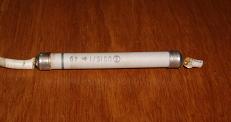
The body of the diode is 0.25 inches in diameter and 2.5 inches long.
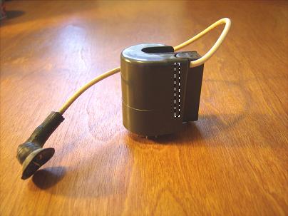
So, naturally, I expected that a high voltage diode that was embedded inside the potted portion of a flyback transformer would likely resemble such a diode. And, at this point, I still expect that often times this is the case. However, I found a flyback where this was definitely not the case:

In this case, here is how I imagined the high voltage diode would likely be positioned within the flyback's case.
We know that the high voltage wire coming from the top of the flyback is driven by one end of a secondary winding of many turns. There may or may not be a high voltage diode between that externally visible wire and the actual end of the secondary winding that drives it. When investigating this flyback I used a procedure that determines whether the flyback includes an internal diode as well as which pin on the bottom of the flyback corresponds to the other end of the secondary. The procedure uses two 9-volt batteries, a voltmeter, and a few bits of wire. The test arrangement looks like this:
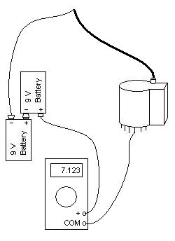
Connect the circuit as shown. The meter should be set to read DC volts as high as 18 volts. For most meters, that is likely to be the 20 VDC range. The wire from the COM (or -) terminal of the voltmeter is touched in turn to each pin on the bottom of the flyback. As long as the voltmeter reads 0 volts, the pin being touched is NOT connected to the high voltage secondary. If the meter reads something around 18 volts, the end of the secondary has been found and the flyback either has no internal diode or the internal diode is shorted. Either way, those who want an AC flyback should be happy with this.
If the meter reads something that is non-zero but substantially less than 18 volts, the end of the secondary has been found and the flyback does have an internal diode. By the way, most of the difference between the 18 volts supplied by the batteries and the reading on the voltmeter represents the forward voltage drop of the internal high voltage diode.
If more than one pin is identified as belonging to the secondary, the secondary simply has one or more taps, normally all near the non-high voltage end.
Having performed this test with my flyback, I determined that it did have an internal diode which I wanted to eliminate.
Unlike most flybacks that I had been looking at, the bottom of this one did not appear as some polymer or epoxy substance from which the pins protruded. Instead, this one had a grey plastic bottom molded from the same type of plastic as the rest of the coil's enclosure. So I decided to pry the plastic bottom off.
Inside, I discovered that this flyback was not potted in some polymer or epoxy material. Instead, it was potted in a rubbery material that was rust brown in color. I soon tried digging at it with my pocket knife and found that it was pretty easily removed in small chunks.
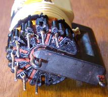
I made a couple of vertical cuts up the front and back through the outer plastic shell and was soon able to remove the plastic shell. After a lot of careful digging around with the knife, I had the entire internal structure exposed with almost none of the potting material remaining. That is when I discovered that this flyback was not at all made as I had imagined. Here is a view of the internals with the potting material removed:

In this next view, I had simply clipped off the high voltage output wire:
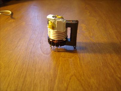
Here are several more images of the exposed coil rotated to afford different views of it:


And for those who might not recognize everything, here the parts are identified:

Here is a shot of the bottom of the coil. The pins were numbered on the black plastic molded part that held the pins. Oddly, they were numbered different there than on the grey plastic molded piece that covered the bottom in the original assembly. That must have made for some confusion wherever these things are manufactured.
Here is a closeup view of the end of the fine wire of the secondary right where it meets the internal diode and a capacitor.
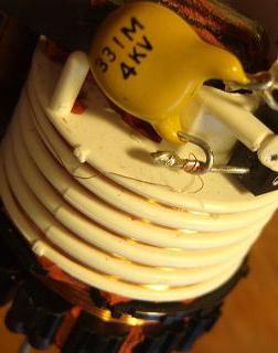
You can see just how fine this wire is.
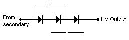
While it is not clearly visible in the photos, pictorially the circuit looks like this:

After electrically checking out the black component with six leads that is labelled "-0619", I determined that it contains three high voltage diodes and the equivalent schematic for the secondary winding circuit looks like this:
Now I will continue on trying to get my oscilloscope to work. But I thought I would post this info on line for the benefit of others who might wonder what a flyback transformer looks like internally, even if not all are made like this one.
Joe
Send comments to:
![]()
