
I purchased an inexpensive graphic LCD display from a seller on eBay. It is a 1.8 inch TFT 128x160 pixel LCD display with 262,144 colors. It came mounted on a printed circuit board with 8 male header pins on one end and holes for 4 more on the other end. The 4 holes provide connections for an SD card slot on the back. Total cost was about $5.00 USD, including shipping.
This display uses a COG (controller on glass) integrated circuit (ST7735S) to carry out all the details of managing the LCD display itself. The display can operate using 12-bit, 16-bit, or 18-bit color.
For purposes of this discussion, here are some images for reference.
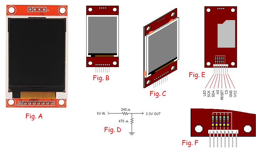
Figure A is a front view of the display as it is sold. The 4 SD card interface holes at the top are empty but the 8 holes at the bottom had male header pins soldered in place that protruded directly out the back side of the board. This means the display could be used in a breadboard application which is what I wanted to do with it but the display would be down flat against the breadboard. I preferred it to be standing upright so I removed the straight male header pins and installed right angle pins. Then the LCD display looked more like Figure B shows it.
Finding data for this display proved more difficult than for most devices I have used. The pins along the bottom are labeled VCC, GND, CS, RESET, A0, SDA, SCK, and LED. Here is a schematic for the printed circuit board.
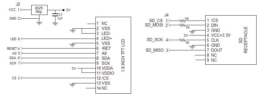
NOTE that the 8-pin connector along the bottom is identified as J2 and the 4-pin connector at the top (the one with no pins installed) is J4.
The board can be externally powered from +5V because it includes a 3V regulator on the board that provides power to both the LCD display module as well as the SD card slot. However, the logic signals to the board should be restricted to 3.3 volt signals. I did accidentally operate mine with 5 volt signals for a short time and consider myself lucky that I did not fry the thing.
To power the LCD display's backlight, I use a 220 ohm resistor as a current limiter but suspect a lower value could be used for greater brightness. The resistor connects between the pin marked LED and the +5 volt supply.
I wanted to interface this LCD display with a PIC18F2550 processor. I use a PIC18F2550 based development board called a BOLT that is sold on eBay. The PIC uses a 20 MHz crystal with a resulting system clock of 48 MHz. Inside the PIC, the system clock is divided by 4 to produce the instruction clock. Most PIC instructions execute in one of these instruction clock cycles. Hence, the PIC executes about 12 million instructions per second or one every 83.3 nanoseconds.
The PIC18F2550 that I use has a bootloader in it that lets it be reloaded via USB in about 2 seconds without ever removing the PIC chip from its socket. Everything is powered by the USB cable from my PC. The bootloader occupies a chunk of the flash memory of the PIC. Consequently, the starting address for a user-written program in the PIC is at 0x800 instead of 0x0. There is a similar offset for interrupt vector.
The LCD display uses SPI. Data is presented to the display on the SDA pin and is clocked by the SCK pin. I have not attempted to read any data from the LCD display. I only write to it. The display has a device select pin (CS) which must be low to cause the LCD display controller to pay attention to the SCK and SDA pins. It is acceptable to just keep CS low all the time if desired. That is what I did.
The LCD display starts its initialization when power is applied or when the RESET signal is pulled low for at least 10 microseconds. My code pulls RESET low for 500 microseconds and then back to high for 500 microseconds before attempting to communicate with the ST7735S controller chip.
There is one more logic signal into the LCD display, A0, which is poorly named. When low, it lets the ST7735S know that the information being sent via SCK and SDA is a command. When high, it indicates that the information being sent is data. Therefore, this is really a register select signal and would typically be called RS.
In my case, I drive the LCD display using RESET, A0, SCK, and SDA.
The LCD display module is held to the printed circuit board using some adhesive that eventually failed when the display was held in an upright position for a long time. So I added some hot glue in a few places as indicated by Figure C where I showed the hot glue in a false orange color.
One simple way to reduce a 5 volt logic signal to 3.3 volts involves the use of two resistors in a simple voltage divider. This is depicted schematically in Figure D. Ideally, the resistor to ground would be exactly twice the value of the input resistor. The ratio of 470 ohms to 240 ohms is close enough to work well.
Adding a lot of resistors to my breadboard to reduce the 5 volt logic signals to 3.3 volts took a lot of valuable space on my breadboard so I added five 470-ohm resistors to the back of the LCD display as shown in Figure E with a close up view in Figure F. Now I need only four 240-ohm resistors on the breadboard for the signals that I do use. The 470-ohm resistor connected to the CS pin serves to hold that signal low all the time.
The SDA signal is the serial data signal. I believe it is used for sending data in either direction. However, in my case, I do not try to read data back so it serves as SDO, serial data out of the PIC.
The SCK signal is the serial clock signal that clocks the data into the LCD controller. The state of the SDA (i.e., SDO) signal is sampled by the LCD controller when the SCK signal transitions from low to high.
When I set out to create a program for this LCD display, I discovered that this page provided good information about essentially the same LCD display but mounted on a different printed circuit board. There is a link on that page that can download some C source code for routines to drive the LCD display.
The datasheet for the ST7735S provided information that added more meaning to the commands that were being sent by the C program to the LCD controller to initialize it. That was my starting point for preparing code in assembly language for the PIC18F2550.
Assembly language offers us the most dense means of programming a computer, but also nearly the most tedious way as well. I did what I could to compact the LCD initialization routine and add at least some documentation about what is going on there.
One aspect of my routines is different from the C routines with regard to the active window of the LCD controller. The LCD controller has registers that describe the current rectangular window within which pixels may be written. When the window's coordinates are established by the microcontroller program, the current pixel writing location is at the top left corner of the window. Following that, as each pixel is written, the current writing location advances pixel by pixel to the right until the right edge of the defined window is reached. Subsequent pixels being written are then directed to the next row of pixels in the defined window. And so it goes, from left to right and from top to bottom until the window has been filled.
The two LCD controller commands that define the window are assigned the symbolic names of LCD_CASET and LCD_RASET in my program. LCD_CASET sets the column limits of the active window while LCD_RASET sets the row limits. Each of these can be followed by 4 data bytes. The first two bytes define the start and the latter two define the end of the row or column range. For some reason, the controller seems to be working with 16 bit numbers despite the fact that the display has only 128 pixels by 160 pixels so the numbers are never larger than 159.
During the LCD initialization routine, LCD_CASET is sent followed by 0 and 127, each expressed as a 16-bit number. This sets the column limits of the active window to the full width of the display. Then LCD_RASET is sent followed by 0 and 159, each also expressed as a 16-bit number. This sets the row limits of the active window to the full height of the display. Therefore, during initialization, the entire display is set to be the active window. The last step of the initialization takes advantage of this setting and clears the LCD screen by writing 20,480 (128 times 160) black pixels to the display.
I discovered that while LCD_CASET can accept 4 data bytes of information to set the left and right limits of the active window, if one sends only the first 2 bytes of data, only the left limit is set and the right limit stays as it had been set previously. A similar trick works for LCD_RASET, allowing only the top of the active window to be set without disturbing the bottom.
Therefore, the easy way to write pixels to any desired X,Y location on the LCD display is to send a LCD_CASET command followed by 2 data bytes describing the X coordinate and then the LCD_RASET command followed by 2 data bytes describing the Y coordinate. Then the LCD_RAMWR command is sent followed by the data bytes describing the color to be written to the pixel.
When I get around to writing characters to the LCD display, I plan to momentarily establish the active window to be a small rectangle to recieve the character's pixels, write the pixels to define the character, and then return the active window to encompass the whole screen.
The LCD controller can be directed to operate in 12-bit color mode, 16-bit color mode, or 18-bit color mode. I chose to use the 16-bit color mode. This uses 5 bits for red, 6 bits for green, and 5 bits for blue color levels, all packed into two bytes.
I originally intended to use the PIC's hardware SPI interface but then discovered that would require dedicating more I/O pins to the interface. Since I wanted to incorporate this LCD display in another project which was rather short on pins, the bit-bang method of SPI looked better for me. My first bit-bang SPI routine used a loop so it was small but had some overhead due to the mechanics of the loop. So I "unrolled" the loop. This resulted in a longer SPI transmit routine but faster execution.
Included in my PIC code is a demo routine called LCDStar. It calls on the other routines to draw a series of 50 straight lines radiating from a central point on the LCD display to a series of target points near the periphery of the display. They are drawn using 4 different colors. In timing tests, these 50 lines are drawn in 121 milliseconds or at a rate of 419 lines per second. Here is what the LCDStar result looks like on the screen:

The total flash memory used for this project is 778 bytes, of which 128 bytes are for the LCDStar demo routine. The LCD driver routines occupy the remaining 650 bytes.
The PIC18 assembly language source code that drives my LCD display (including the demo routine called LCDStar) can be seen here. You are free to use it in any way that you wish. I would appreciate being given credit if you use it, but if you don't, it won't really matter much.
Later, I will add more description here about how I happened to develop this code. It was not in the usual way.
Send comments to:
![]()
