For a verbal description click here.
"That's a pretty good trick. Nothing in the real world is ever infinite or zero. If you've got a detector that really has in infinite impedance you might win the Nobel prize." Nope! Not a Nobel prize winner here. Just a circuit that is so old it dates back to the 1920s when anything that was too large to be measured with the primitive meters of that time was thought of as infinite.Parts.
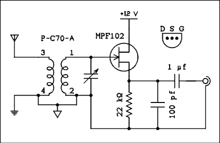
You can use the same coil and capacitor for this that you used for the drain detector and crystal set. If you didn't build the crystal set you can go back there to find out about coils. Whether you elect to scavenge parts from a transistor radio, Roll your own, or buy, this circuit will work with whatever coil you put in it. The transistor is the venerable MPF102. As far as I know it is still available and is still being used by hobbyist the world over. None of the other parts are remarkable. Here's the circuit.

For a verbal description click here.
Someone is already thinking or maybe even saying that I have mislabeled the transistor leads. In the case of the MPF102 it doesn't make any difference. Now that the source is the output it would make sense to switch the drain and source back but I used the same breadboard setup. Feel free to change them if you want to.The transistor is biased very close to cutoff. When an RF signal appears at the gate the negative half-cycles drive the transistor totally into cutoff. The positive ones increase the drain current which is also the source current. The source current is a half wave rectified version of the input signal. The 100 pf capacitor smoothes out the RF cycles and the audio modulation is left.
When tuned to the station who's transmitter is several miles away this circuit seemed to deliver about the same amount of audio output as the drain detector. But the station who's towers I can see by looking out my back window produced much louder audio. I would say it was overloading the drain detector.
This page last updated August 3, 2006. v