BURST FIRE TRIGGER MECHANISM
BURST FIRE TRIGGER MECHANISM
OVERVIEW
The gun is semi-automatic and preferably is an M-16/AR-15. It includes a
firing trigger, frame and trigger guard, as well as a multiple firing gun
trigger extension assembly. The assembly includes an elongated trigger
guard bar incorporated into the trigger guard below the gun trigger, and a
trigger-actuating component rotatably secured to the guard bar and
including a supplemental trigger below the guard bar and a number of
spaced trigger-actuating fingers disposed in an arc above the supplemental
trigger. The fingers during their rotation can contact the gun trigger
directly to affect sequential firing of the gun or can sequentially strike
an interposed trip lever which is rotatably secured to the guard bar, the
trip lever thereupon sequentially striking the gun trigger to effect the
firing. Suitable springs and the like can return the trip lever and other
parts to the resting position. A second supplemental trigger can be
connected above the fingers to effect a second series of sequential
firing.

DESCRIPTION
BACKGROUND
Various semi-automatic weapons such as rifles, automatic pistols and the
like are currently available. With these weapons the triggers must be
sequentially pulled in order to cause sequential firing. The speed of
firing is limited by the gunner's ability to squeeze the trigger, fire,
release the trigger and repeat the sequence. Such firing is not very
rapid. Such weapons can be rendered fully automatic by modifying their
firing mechanism. By full automatic is meant that once the trigger is in
the firing position, the gun fires sequentially until the trigger is
released. However, such weapons, except for military and certain law
enforcement use, are generally illegal.
It would be desirable to provide a simple, efficient, inexpensive and
durable device to enable a gunner to sequentially fire a semi-automatic
weapon at an increased speed, without modifying the gun to the full
automatic mode. For safety's sake and for sporting purposes, the device
should limit the number of shots fired in a sequence to a reasonably small
number, for example, 2-5 shots, with a pause or separate action being
required before the sequence could be re-initiated. Such a device would be
very helpful in hunting large, dangerous game such as African big game,
grizzly bears and Kodiak bears and the like, where the hunter could be in
serious danger from a charging animal if the hunter could not shoot the
semi-automatic weapon rapidly and accurately enough.
SUMMARY
The improved semi-automatic gun of the present invention bearing the
multiple firing trigger extension assembly of the present invention
satisfies all the foregoing needs. The gun and trigger extension assembly
are substantially as set forth in the Abstract. Thus, the gun preferably
is an M-16/AR-15 rifle and includes a gun trigger, frame with trigger
guard and the trigger extension assembly of the invention which is
incorporated into the trigger guard. That assembly may be fabricated of
steel or the like and includes an elongated trigger guard bar below the
gun trigger and rotatably bearing a preferably one-piece trigger-actuating
component which includes a supplemental trigger below the guard bar and a
plurality of spaced trigger-actuating fingers disposed in an arc
thereabove. The fingers during their rotation, as by pulling the
supplemential trigger, either directly or indirectly sequentially strike
and move the gun trigger to sequentially fire the gun. In the latter case,
a trip lever is rotatably interposed between the gun trigger and fingers
and is sequentially struck by the fingers so as to itself sequentially
strike the trigger. Return springs and the like can be provided to bias
the gun trigger, lever and supplemental trigger to the resting position.
In one embodiment a second supplemental trigger is connected to the
trigger-actuating component above the fingers and is used to rotate the
component in one direction for one set of sequential firing, whereupon the
first supplemental trigger is used to rotate the component in the opposite
direction for a second set of sequential firing.
Further features of the improved multiple firing gun and trigger extension
assembly of the present invention are set forth in the following detailed
description and accompanying drawings.
DRAWINGS
FIG. 1 is a schematic side elevation of a preferred embodiment of the
multiple-firing semi-automatic gun of the present invention bearing a
first preferred embodiment of the trigger extension assembly of the
present invention;
FIG. 2 is an enlarged schematic side elevation, partly broken away, of the
novel trigger extension assembly of FIG. 1;
FIG. 3 is an enlarged schematic side elevation, partly broken away, of a
second preferred embodiment of the novel trigger extension assembly of the
present invention;
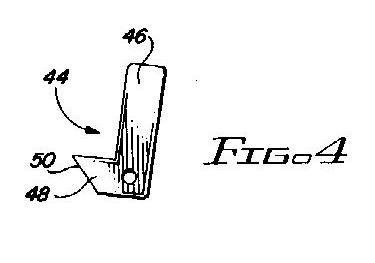
FIG. 4 is a schematic side elevation of the trip lever of FIG. 2;
FIG. 5 is a schematic side elevation of a modified form of the trip lever
of the invention; and,
FIG. 6 is an enlarged schematic side elevation, partly broken away, of a
third preferred embodiment of the novel trigger extension assembly of the
present invention.
DETAILED DESCRIPTION
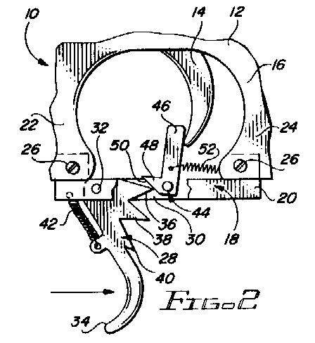
FIGS. 1, 2 and 4
Now referring more particularly to FIGS. 1, 2 and 4 of the drawings, a
first preferred embodiment of each of the multiple firing gun and trigger
extension assembly of the present invention is depicted therein. Thus, an
M-16/AR-15 semi-automatic rifle 10 is shown, which is of standard
construction, including a frame 12, barrel 13 and trigger 14. However, the
lower part of the trigger guard 16 of gun 10 has been modified to include
the novel trigger extension assembly 18 of the present invention.
Assembly 18 includes (FIG. 2) an elongated about horizontal trigger guard
bar 20 substituting for the original M-16/AR-15 bottom trigger guard bar
(not shown) and secured to depending trigger guard portions 22 and 24 by
screws 26 or the like. Bar 20 has a trigger-actuating component 28
rotatably secured thereto. For this purpose, bar 20 may have a vertical
slot 30 therein in which component 28 is secured by a cross pin 32.
Component 28 preferably is unitary, that is, of one-piece construction and
includes a supplemental trigger 34 below bar 20 and three spaced, narrow,
triangular pointed fingers 36, 38 and 40 disposed in an arc above trigger
34. Trigger 34 is urged into a forward resting position by spring 42
connected to the front of component 28 and to bar 20 (FIG. 2).
Interposed between trigger 14 and fingers 36, 38 and 40 is a generally
L-shaped trip lever 44 (FIG. 4) rotatably secured in slot 30 to bar 20,
with the upper arm 46 thereof directly in front of trigger 14 and the
lower arm 48 thereof in the path of rotation of fingers 36, 38 and 40. Arm
48 has a downwardly and rearwardly sloped front face 50 against which the
point of each finger 36, 38 and 40 sequentially bears to cause arm 46 to
sequentially pivot rearwardly and sequentially move trigger 44 rearwardly
to sequentially fire gun 10.
Spring 52 allows trigger 14 and arm 46 to return to the resting about to be
fired position between sequential urgings into the firing position by
fingers 36, 38 and 40. Thus, trigger 34 can be very rapidly pulled in the
direction of the arrow in FIG. 2 to very rapidly cause fingers 36, 38 and
40 to sequentially push arm 46 against trigger 14, with forward movements
of trigger 14 therebetween, thereby very rapidly firing 3 shots from gun
10. Spring 42 then returns trigger 34 and fingers 36, 38 and 40, lever 44
and trigger 14 automatically to the resting position for refiring. Sets of
3 shots each can rapidly follow upon each other. The single directional
movement of trigger 34 to effect each set of 3 shots is considerably
faster time-wise to make than having to move trigger 14 by hand back and
forth for each shot in order to cause sequential firing of gun 10. Yet
each set of shots is limited to 3 for safety purposes. Accordingly, the
improved multiple firing gun 10 with assembly 18 therein is of improved
construction, performance and safety.
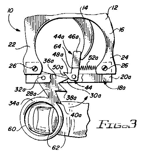
FIG. 3
A second preferred embodiment of the improved multiple-firing trigger
extension assembly of the present invention is schematically depicted
therein mounted on rifle 10 in place of assembly 18. Thus, assembly 18a is
shown. Components of assembly 18a which are similar to those of assembly
18 bear the same numerals but are succeeded by the letter "a".
Assembly 18a is substantially identical to assembly 18 except that assembly
18a does not have a return spring, such as 42, for trigger 34a . Instead,
trigger 34a bears a ring 60 in which the gunner inserts his or her finger
62 and by which the gunner can urge trigger 34a fully forward into the
resting ready-to-fire position. Also, arm 46a may have a groove 64 in it
to facilitate connection of spring 52a thereto. Bar 20a, component 28a,
fingers 36a, 38a and 40a and lever 44a are otherwise identical to those
components of assembly 18 and have similar properties and advantages.
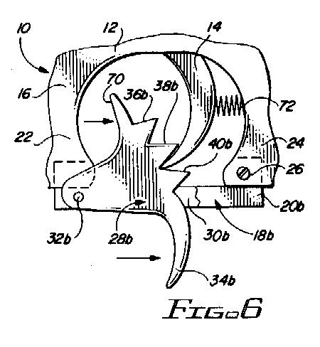
FIG. 6
A third preferred embodiment of the multiple firing trigger extension
assembly of the present invention is schematically depicted in FIG. 6.
Thus, assembly 18b is shown therein connected to gun 10 in place of
assemblies 18 and 18a. Components thereof similar to those of assembly 18
or 18a bear the same numerals but are succeeded by the letter "b".
Assembly 18b is substantially identical to assembly 18 except that no
return spring for supplemental trigger 34b is provided. Moreover, a second
supplemental trigger 70 is integrally connected to component 28b above
fingers 36b, 38b and 40b. In addition, fingers 36b, 38b and 40b are of
more or less stepped configuration instead of being narrow, triangular and
pointed. No trip lever such as 44 is provided. Instead fingers 36b, 38b
and 40b directly sequentially strike and move trigger 14 to sequentially
fire gun 10. A return spring 72 may be provided behind trigger 14 in guard
16 to rapidly urge it into the proper forward position between firings.
It will be noted that when trigger 34b is pulled rearwardly in the
direction of the arrow, a set of 3 shots is fired by rotation of fingers
36b, 38b, 38b and 40b counterclockwise to effect sequential activation of
trigger 14. When trigger 34b reaches the rear end of the path of travel,
trigger 70 can then be pulled rearwardly to cause another set of 3 shots
to be sequentially fired, fingers 36b, 38b and 40b rotating clockwise to
effect such firing. Triggers 70 and 34b can be simultaneously contacted by
the forefinger and middle finger, respectively, and worked back and forth,
so that the described repetition of sets of 3 shots can be continued very
rapidly until gun 10's magazine 74 (FIG. 1) is exhausted. Thus, very rapid
controlled shooting can be carried out. Assembly 18b also has the other
advantages of assemblies 18 and 18a.
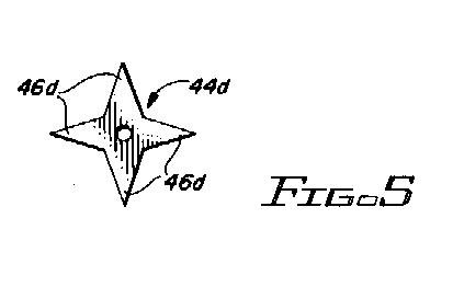
FIG. 5
FIG. 5 schematically illustrates a modified form of the trip lever such as
is utilized in the embodiments of FIGS. 2 and 3. Thus, trip lever 44d is
shown. Instead of being L-shaped, as are levers 44 and 44a, lever 44d is
in the form of a 4-pointed star rotatably supported through its center at
a suitable location on or above bar 20 (not shown). Fingers 36, 38 and 40
or their equivalents can rotate lever 44d by contact with its arms 46d,
which arms 46d in turn can effect the desired movement of trigger 14.
By the term M-16/AR-15 is meant the M-16 rifle and the civilian version
thereof which is known as the AR-15 rifle.
Various modifications, changes, alterations and additions can be made in
the improved multiple-firing gun and trigger extension assembly of the
present invention, their components and parameters. All such
modifications, changes, alterations and additions as are within the scope
of the appended claims form part of the present invention.
US PATENT 4,685,379 TRONCOSO

© JANUARY 2000, ON A NEED TO KNOW BASIS, all rights reserved.


