
I started the rear axle first. I removed the differential cover, which was a little challenging considering some of the bolts were deformed from abuse. I had to file a couple of them back to a hex shape before I could get a wrench on them. Next, I removed the back tires, and brake drums. The brakes looked like they had 30,000 miles on them, yet had less than 1,500. People have told me that mud and silt can really do a number on drum brakes, and they're right, but that will be a different story. I needed to pull the axle shafts out, at least far enough to clear the gear carrier before I could get the carrier out. To do this, I aligned the hole in the axle flange with the nuts on the axle retaining plate. I stuck a socket through the hole and removed the four nuts.
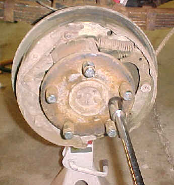
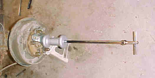
To get the shafts out, I needed an axle shaft puller. This consisted of a slide hammer and a flange adapter that bolted to the wheel flange. I don't think you'll need a puller for stock axles. I think the bearings on a stock axle will have separate races, so the axle shaft will just about fall out when the retaining plate is loose. My axles have a 1 piece bearing and race, which are a little tougher to get out. Auto-Zone had the slide hammer and axle flange adapter available on a deposit/loan program that allows you to use the tools for no cost, or you can just buy them for the cost of the deposit. I decided that the $35.00 deposit was cheap enough, so I kept them. Once I bolted the axle flange to the axle flange (that sounds weird) and gave the slide hammer a slide (that sounds weird, too) the axle came out smooth as butter.
I moved back under the Jeep and used a hammer and a center punch to mark the
top of each carrier bearing cap with three little dots in the shape of an arrow
that pointed outward. That way I could replace the bearing caps in there original
locations during reassembly. It is important to keep them in there original
locations, in the same orientation. I removed the caps and placed them off to
the side. To get the carrier out I used a long pry bar, and with a little prying
it popped out. Be careful if you've never done this before. The carrier can
be tough to get loose, but once it starts moving, it might just pop all the
way out, so be ready to catch it. The races are not retained in anyway, so when
the carrier comes out, the races will just fall out if you don't hang onto them.
To get an idea of how tight the carrier is supposed to fit, I put it right back
in, and then pulled it back out again. This gave me a feel for how tight I should
get the new assembly. I'll set my carrier a bit tighter because all the bearings
will be new and will give a little once they break in. I have yet to here or
read of any setting or guideline for how tight the carrier should be in the
housing. I think the instruction manual says "tight, but not so tight that is
overly difficult to install", or something to that effect.
Now that the carrier was out, I started on the pinion. I used a pipe wrench to hold the yoke and used an impact wrench with a 1 1/8" socket to loosen the pinion nut. Once the nut was off, I tapped on the end of the pinion and it slide out the back of the axle housing very easily. Along with the pinion came the shims that determine pinion pre-load. The preload shims totaled .060". The pinion uses two bearings. One bearing is pressed on the pinion right up against the gear end. This bearing came out with the pinion. The second, a looser fitting bearing, stayed in the axle housing. To get the second bearing out of the axle housing, I had to remove the pinion seal. I used a pry bar to convince the seal to come out, then the bearing could be removed.
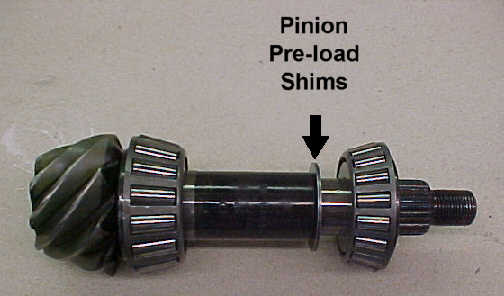
The only thing still remaining in the axle housing are the two pinion bearing races. I originally tried to use a long screwdriver to drive the races out, but the handle of the screwdriver absorbed too much of the hammer blow, and the races didn't budge. I ended up buying a long punch, and that worked well. The amount of area exposed on the back of the races is small, and I had to hit them pretty good to move them. The inner most bearing has shims behind it. These shims are what determine the pinion depth. I really beat the crap out of the shims trying to get the race out. The pinion depth shims totaled .037".
Now that the housing is empty, it was time to clean. I used brake cleaner and compressed air to clean the housing. There are some passageways in the pinion area of the housing that collected a bunch of fine metal shavings. Be sure to clean these out.
With the housing clean and all the old parts out, it was time to explore.
I used my bearing splitter and press to remove the bearing from the old pinion.
This was just for practice, since I've never used a press or a bearing splitter
before, and I have no reason to do anything with the old pinion as none of it
gets re-used. I then turned around and put the bearing right back on. The bearing
splitter works great. It gets under the inner race of the bearing with the tiniest
sliver of metal, and can be pulled on with a vengeance. Matco Tools makes a
push/pull accessory for the splitter, which is rated at 13 tons! (and costs
about 12 tons)
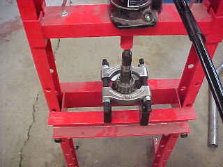
One thing I wanted to determine was the amount of shims the stock gear carrier had on it, so I attempted to pull these bearings off. These bearing are on pretty good, so don't bother messing around trying to make due with anything less then a big gear puller. With the bearing splitter round the base of the bearing, I attached an array of crap to the splitter to pull on the bearing. I originally tried to use parts of my harmonic balancer puller and my axle puller, but they did not develop enough force to loosen the bearings. Then I tried a 5" bearing puller, with no luck. After a lot of screwing around, I finally bought a 10" gear puller and that did the trick.
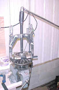
I used one of the race drivers and a scrap piece of steel on the end of the carrier to provide a place for the puller's screw to push on. Once the bearings were off, I measured the shims. The driver's side had .037"of shims; the passenger side had .042".
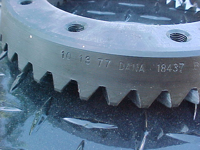 I removed the old ring gear just for the sack of comparing the old gears with the new. The old gears are 3.54:1 and the new gears are 4.89:1. You can see the difference in the pinion gear diameter. As gear ratios get higher, the pinion gets smaller. For this reason some people stay way from gears this high or higher. The gear ratio can be determined in two ways. You can either count the teeth on both the ring gear and the pinion, or you can look at the markings on the edge of the ring gear. Both the existing gears and the new are Dana Spicer gears. They have similar markings; both start with the date of manufacture and continuing with more information, including the tooth count of the ring gear and the tooth count of the pinion. To get the ratio, divide the ring gear tooth count by the pinion gear tooth count.
First off, lets go over a few terms, and how they apply specifically to a Dana 44 axle.
Pinion Depth - This is the distance the pinion extends into the axle housing. This influences the gear pattern, and is what makes the whole deal tricky. You can't really check the pinion depth without installing everything else. Therefore, it is very labor intensive to adjust the pinion depth. For each attempt at setting the pinion depth, you have to assemble the entire differential, and then check the pattern, and teardown the entire assembly if the pattern is perfect. You can only get an accurate reading of pinion depth with pinion bearing pre-load and backlash within tolerances, so changing the pinion depth once may include several shim changes on the carrier.
Pinion Bearing Pre-load - This is the amount of tension on the pinion bearings. Pre-load is adjusted by adding and removing shims from the shaft of the pinion. The shims determine how much pressure the outer pinion bearing can exert on the race. Adding more shims reduces the pressure, thereby lowering the pre-load. Pre-load is measured by turning the pinion with an inch pound torque wrench. Final pre-load should be between 14 to 19 inch-pounds, with the pinion nut tightened to 250 foot-pounds.
Backlash - This is the amount of rotational movement (or play) allowed because of space between the pinion and the ring gear. It is measured with a dial indicator. It is adjusted by moving the ring gear closer to or farther from the pinion by changing the amount of shims between the carrier bearings and the carrier. Backlash should be between .006"-.010".
Gear Pattern - This is the final measure of gear set-up. You apply a gear marking compound to the teeth of the ring gear, then rotate the ring gear past the pinion gear and look at the contact pattern on the teeth of the gear. The position of the contact pattern is the only indicator of gear alignment. The ideal pattern is centered on the tooth from Face to Flank. The pattern from Toe to Heel is not important, and can be miss leading. Toe to Heel alignment is machined into the housing, and is not adjustable without more machining. As long as the pinion contacts the center of the ring gear teeth from Face to Flank, or tip of the tooth to the base of the tooth, all will be good.
The first thing I did was to put the new pinion bearing's races in. The inner race requires some shims to set the pinion depth. My first attempt at setting pinion depth was just a guess. A good guideline is to start with the same amount of shims that were under the race before. Odds of getting the depth right the first time are slim anyways, so feel free to take a guess. I started with .044" of shims underneath the inner pinion bearing's race. The outer pinion bearing's race does not require shims, as pro-load is set with shims on the pinion shaft. Next, I put the new inner pinion bearing on the pinion shaft. There are no shims here either. The outer bearing does not go on until the pinion is in the housing. Now I was ready to begin installation, so I installed the pinion into the axle housing. The outer pinion bearing is a looser fit then the other bearings, and I used the pinion yoke and nut to push the bearing onto the shaft. I first I put the bearing on the shaft, then slide the yoke on and tapped it with a soft-faced hammer. Once it was on enough to start the pinion nut, I just tighten the nut to push the bearing on the rest of the way. (I reused the old pinion nut for all my trials.
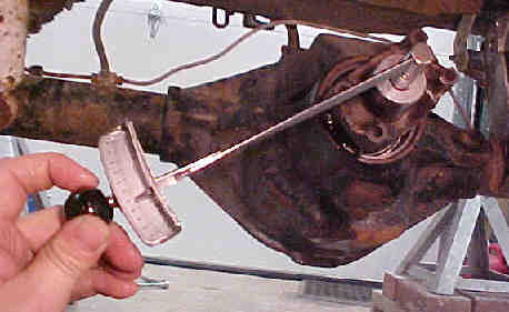 Once I get the gear pattern right, I will install the new nut. ) I tightened the pinion nut until it was snug then I checked the pre-load by using my inch pound torque wrench to rotate the pinion. I continued to tighten the nut until the pre-load measured between 14 to 19 inch-lbs. This is NOT how you set the pre-load for the final assembly. Pre-load is set by placing shims on the pinion shaft that stop the outer pinion bearing from pushing too hard on it's race, then the pinion nut is tighten to 250 ft-lbs. You then measure the pre-load on the pinion by rotating it. You need to adjust the shims until the pre-load is correct. You don't have to set the pre-load this way until the gear pattern is good, otherwise you'll be messing around with the pre-load shims every time you change your pinion depth. I didn't catch on to this idea until I was finishing up the rear axle, but I did the front this way and it saved a ton of time. Be careful not to over tighten the pinion nut if you're unsure of the preload shims (or don't have any in yet). Over tightening the nut can damage the bearing.
Now that I have the pinion ready, I moved onto the Detroit Locker. I cleaned the outside with break cleaner, and checked the machined surfaces for anything that would keep the ring gear or the bearings from seating properly. If there are any burs or other obstructions, you will have to file them off. I bolted the ring gear on to the locker with the new bolts a moderate dabs of thread locking goo, all included in the install kit. I also followed the advice given in the instruction manual and put a little gear lube under the head of the ring gear bolts to get an accurate torque reading when I tightened down them to 55 foot-lbs. I placed some shims under the carrier bearings and pressed the bearings on. Before I pressed on the bearings, I gave both the carrier and the bearings a coating of gear lube to make installing and removing the bearing a little easier. The amount of shims to use under the carrier bearings is a guess, just like the pinion depth. You can use the same amount of shims that were under the old bearings. I started with .040" on the drivers side and .030" on the passenger side.

 With the locker ready to go, I crawled under the Jeep and tried to set it in the axle housing. I had too many shims because I couldn't squeeze the locker in the housing, so I had to remove some shims. This is the part I had the most trouble with. I tried several pieces of apparatus to try and pull the bearing off, but to no avail. The only way I found to get the carrier bearings off is to use a large bearing/gear puller in conjunction with the bearing splitter. I don't think you can get the bearing off without a bearing splitter. You can use a press if you have a lot of blocks and stuff to support the splitter, but I couldn't come up with a way of supporting it.
After getting the bearing off, I adjusted the shims and replaced the bearings with the press. I lessened the drivers side shim pack down to .010". I didn't change the passenger side at all yet. I put the locker in the housing, this time it was a little loose fitting, but I thought I'd go with it for now, so I bolted the bearing caps down to 60 foot-lbs. I measured the backlash, and it was .020" which was too much.


Want to continue on to page 3?
Want to send me e-mail?
Want to go back to page 1?
Want to go to the frontpage?