For a verbal description of newly added parts click here.
For a verbal description of the complete diagram click here.
The first tube in an All American Five converts the frequency of the incoming station to the Intermediate Frequency (IF). In the early years of radio this conversion was known as heterodyning. The principle of heterodyning had been developed by Edwin Armstrong in the 19 teens and an early version was offered to the public as early as 1919 but it really didn't catch on in the consumer market until the late 1920s. The All American 5 is known as a super heterodyne receiver.Here is a partial diagram of the AA 5 as of this lesson.
For a verbal description of newly added parts click here.
For a verbal description of the complete diagram click here.
The symbol in the upper left corner of the figure is the loop antenna. This is an inductor wound large and flat as shown in the picture below. This antenna is 8 inches long by 4 inches wide. This was mounted on the back of the radio case and was referred to in advertising as the built in antenna or sometimes the built in aerial.The magnetic field from the radio station tower passes through this coil and induces a voltage in it. The variable capacitor tunes the coil to the frequency of the desired station and that station's signal is the strongest one induced in the coil, all other things being equal. 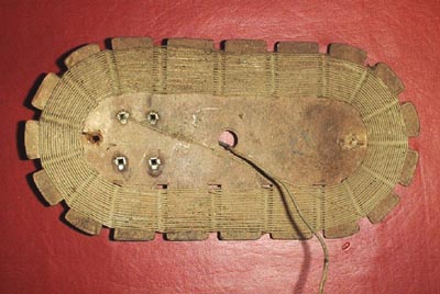
For a verbal description click here.
You might assume that the rest of the radio has tuned circuits set to the frequency of the station you want to listen to. That's exactly what radios did before about 1930 (although they didn't have built in antennas back then). These were known as TRF for Tuned Radio Frequency receivers. If you want more information on TRF circuits follow this link then use your back button to return here.
The large coil serves both as a means to pick the radio signal out of the air and a tuned circuit that begins the process of selecting the one station out of many that you want to listen to. The signal from the antenna is fed to grid number 3 of the converter tube. For more detailed information on the process of frequency conversion, or heterodyning, click here then use your back button to return.
The first two grids of the converter tube form an oscillator. As the radio is tuned across the dial the frequency of this oscillator is changed so as to be 455 kc above the desired station. This is termed the "local oscillator". So if we want to listen to a station on 780 kc we must tune our local oscillator to 780 kc + 455 kc = 1235 kc. The 1235 kc local oscillator combines with the incoming station at 780 to produce two new frequencies at 455 kc and 2015 kc. The tuned circuit in the plate of the converter tube selects the frequency at 455 kc and rejects all others. A station coming in at 770 kc will combine with the oscillator to produce 1235 - 770 = 465 kc. This frequency will be greatly reduced in power by the four tuned circuits in the two IF transformers, but I'm getting ahead of myself. Similarly, the station on 790 will combine with the local oscillator to produce 435 kc which will be reduced in power so you will hear only the station on 780 kc. The frequency of 455 kc is in-between the station's frequency and the audio frequencies so it is called the "Intermediate Frequency" or just IF for short.
To say "the IF frequency is to be redundant along with ATM machine, PIN number, SAT test, SEC conference, HIV virus, and a thousand others that you can hear all the time even on the radio and TV.How the Converter Works.
The 6BE6/6SA7 converter has 5 grids making it a heptode or 7 element tube. Grids 2 and 4 are tied together inside the tube and grid 5 is tied to the cathode. That's how they can make it work in a 7 pin tube. In the 6SA7 grid 5 is brought out to its own pin. (They need 2 pins for the heater leaving only 5 for the other elements of the tube.)The schematic diagram appears here again so you won't have to keep scrolling up and down. The cathode and the first two grids work like a triode tube and are the local oscillator. The circuit is called a Hartley oscillator because it uses a tapped inductor. The cathode goes to the tap and the first grid, called the oscillator grid, receives signal which is coupled from the top of the oscillator coil.
The cathode current flows through a few turns at the ground, or low, end of the coil. The magnetic field induces voltage in the rest of the coil. The coil is tuned by one section of the variable capacitor and the alternating voltage which appears across the coil has the frequency to which the coil is tuned. The voltage which is applied to the grid is enough to drive the cathode current of the tube from saturation to cutoff. The pulses of cathode current flow through the lower turns of the coil and maintain the oscillation. When the alternating voltage at the top end of the coil swings positive the grid is driven slightly positive and begins to conduct current like a diode. (The grid is attracting electrons to its self and therefor acts like the plate of a diode.) The 220 pf capacitor charges up so the most positive voltage at the grid is just barely positive and most of the time the grid voltage is negative. A DC meter connected to the grid with proper isolation so it won't short out the AC, will indicate the average voltage which may be anywhere from -5 to -40 volts. So the cathode current is flowing in short pulses at the oscillator frequency. Since the cathode is the only source of electrons in the tube the plate current is also flowing in short pulses with little or no current in-between pulses.Grid 2 is connected to B+ and acts like a plate but it is a leaky plate. Electrons pass on through it to go on and be effected by the remaining 3 grids. Grid 3 is where the station's signal comes in from the loop antenna. Because the oscillator signal is over driving the tube the sum and difference frequencies appear. Grid 4 is connected to B+ and so accelerates the electrons on there way to the plate.
Sometimes the impact of electrons on the plate causes electrons already there to be knocked loose. This is called secondary emission. If grid 5, called the suppressor grid, were not present these secondary electrons would go to the screen grid, grid 4, and take away from the plate current. There are times in the AC cycle when the plate voltage is actually less than the screen voltage. The suppressor grid, which is tied to the cathode, is negative enough to cause the secondary electrons to go back to the plate because they have no where else to go. The wires of grid 5 are widely spaced so it has little effect on the high velocity electrons on their way to the plate.
The tuned circuit in the plate of the converter tube is tuned to 455 kc and is the primary of the only IF transformer on the diagram. The operation of the IF transformers and amplifier will be covered in the next lesson.
Previous; Introduction and Power Supply.
Or use your "Back" button to return to where you were.
Thank you for visiting my page at Angelfire.
Please come back and visit again!This site begun March 14, 2001
This page last updated August 1, 2002