Breadboarding.
The noun and verb "breadboard" go back to the earliest days of radio when many things were different. One thing was that most households baked their own bread. It was baked in loaves which had to be cut with a large sharp knife. To avoid cutting up the tops of tables and counters the bread was placed on a wooden board for cutting. These bread cutting boards became the platform for building radio receivers and transmitters. We would call it primitive today, small nails were driven into the board and wires wrapped around them. I don't know if they were soldered or not. I may be old but not that old. Anyway as years passed and construction techniques improved the style of building in which all components were visible and accessible on top of the construction base took on the name breadboarding.What method of breadboarding should you use? That depends on what you have.
- You could do it the old fashioned way and mount tube sockets on standoffs, so you could get to the terminal lugs, and drive nails into a piece of wood. Hardwood would hold the small nails better than plywood. I can't vouch for the quality of the electrical connections you would get with this method.
- The breadboard shown in the photograph was made by the DeVry Technical Institute back in the sixties. It, the institute, has been taken over and renamed several times since then. This breadboard has been modified for integrated circuits and then partially unmodified so I could use it with vacuum tubes again. The edge connector is for testing the modules that plug into my audio preamplifier. But that's another story. If you don't have one of these the chances are slim you could ever buy one even on eBay. Anyone who had one and lost interest in using it either threw it away or gave it away. Someone like me who still has a use for it wouldn't sell it for any amount of money; well, maybe a million dollars. It comfortably holds two tubes although you can get 4 miniature tubes on it.
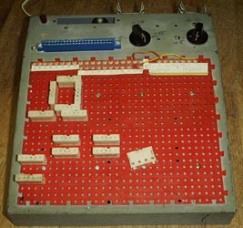
The white blocks are called Modular Connectors. They can be placed anywhere on the red panel. They have a spring bronze clip inside which grips and holds wires which are inserted into one of the 5 holes in the connector. All 5 holes are electrically connected together.
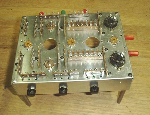
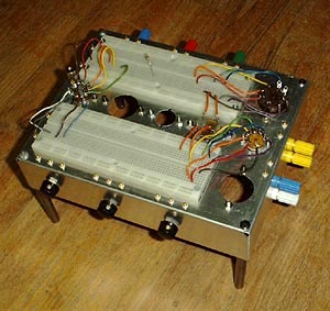
- The idea for the "Practical Breadboard for Vacuum Tube Circuits" came to me as I was preparing these pages for uploading. It occurred to me that two of those IC breadboarding sockets (which are available from many sources) could be placed parallel to each other with tube sockets mounted upside down between them. The chassis would have to be deep enough to allow the tubes to be plugged in underneath. Wires could be soldered to the tube socket terminals to run over to the breadboarding sockets. I have constructed such a device and you can see how to duplicate it by clicking here.
After using this breadboard for several months I have found that it is not as practical as I had first thought. For one thing it is hard to get a good ground. But the main problem is that the IC socket is just too dense for tube circuits. The parts are so large that you can only use about 10% of the socket holes. The other main problem is stray capacitance. Each contact point has about 20 pf of capacitance to chassis and about the same to the adjacent contact. That's not a whole lot in low impedance transistor and IC circuits but it's a lot for tubes. It's enough to totally de-tune an IF transformer or throw an oscillator way off frequency.
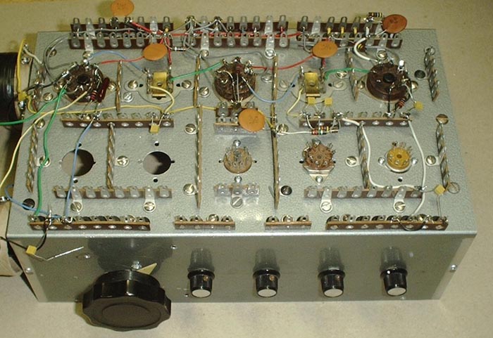
- The vacuum tube electronics labs at the University of Florida used a bunch of terminal strips and tube sockets mounted on top of an aluminum chassis. Circuits were built by soldering components in place. Don't wrap the wires around just stick them through the eyes, bend the wire 90 degrees and tack it to the terminal with a small amount of solder. As in the method above the tube sockets would be mounted upside down.