 Drives
Dell™ OptiPlex™ GX620
User's Guide
Your computer supports:

|
NOTE: For information on installing D-module drives, see the documentation that came with your optional device. |
Serial ATA hard drives should be connected to the connector labeled "SATA0" on the system board.
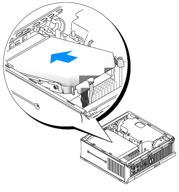
When you install a drive, you connect two cables—a DC power cable and a data cable—to the back of the drive and to the system board.
|
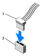
Serial ATA Connector |

|
1 |
interface cable connector |
2 |
interface connector |
Most interface connectors are keyed for correct insertion; that is, a notch or a missing pin on one connector matches a tab or a filled-in hole on the other connector. Keyed connectors ensure that the pin-1 wire in the cable goes to the pin-1 end of the connector. The pin-1 end of a connector on a board or a card is usually indicated by a silk-screened "1"printed directly on the board or card.
|
System Board Power Connector |
Serial ATA Power Connector |

|

|
1 |
power cable |
2 |
power input connector |
When removing an IDE drive data cable, grasp the colored pull-tab and pull until the connector detaches.
When connecting and disconnecting a serial ATA data cable, hold the cable by the black connector at each end.
Like IDE connectors, the serial ATA interface connectors are keyed for correct insertion; that is, a notch or a missing pin on one connector matches a tab or a filled-in hole on the other connector.


|
CAUTION: Before you begin any of the procedures in this section, follow the safety instructions in the Product Information Guide. |

|
CAUTION: To guard against electrical shock, always unplug your computer from the power supply before removing the hard drive. |

|
NOTICE: To prevent static damage to components inside your computer, discharge static electricity from your body before you touch any of your computer's electronic components. You can do so by touching an unpainted metal surface on the computer chassis. |

|
NOTICE: To avoid damage to the drive, do not set it on a hard surface. Instead, set the drive on a surface, such as a foam pad, that will sufficiently cushion it. |

|
1 |
hard drive |
|
2 |
drive rails (2) |
|
3 |
power cable connector |
|
4 |
data cable connector |

|
1 |
drive |
|
2 |
drive rails (2) |
|
3 |
screws (4) |

|
NOTICE: Serial ATA data and power connectors are keyed for correct insertion; that is, a notch or a missing pin on one connector matches a tab or a filled-in hole on the other connector. When connecting cables to a drive, ensure that the connectors are oriented properly before you attach the cables to the drive. |

See the documentation that came with the drive for instructions on installing any software required for drive operation.
For instructions, see the documentation that came with your operating system.
For instructions, see the documentation that came with your operating system.