After the incoming station has been converted to 455 kc the intermediate frequency (IF) stage operates on it. This is where most of the gain (increasing the power of the signal) and selectivity (discrimination against other stations) occurs.The gain part is fairly easy. This amplifier doesn't have to be changed in frequency so it can be tuned up for best gain. It is also easy to keep the input and output sides shielded from each other so oscillation (the same thing as feedback in a PA system) will not happen.
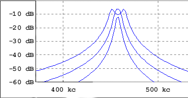
Selectivity comes from the two IF transformers. Each one has two tuned circuits making a total of 4 which is plenty for an AM radio. In each transformer the two circuits are coupled magnetically. If you have one of the older large type you can easily take it apart without doing any damage (provided you are careful with it). Remove the hex nut on top and gently slide the guts out. The smaller kind are more difficult to get apart and have an annoying tendency to fall apart in your hands while you are examining them. The ceramic thing at the top is a dual trimmer capacitor used to adjust the frequency of the individual tuned circuits. What is most likely to strike you is how far apart the coils are. You might assume that if they were closer together more signal would be coupled from one to the other. Not so! If the coils were closer together the circuits would be over coupled and a double humped response curve would result. Feast your baby blues on the figure below.
The horizontal axis is frequency and the vertical axis is dB which can represent voltage or power. When the two coils are close together the response has two peaks with a dip in the middle. Not good. If the two coils are too far apart the circuits will be under coupled. Although this gives a narrow bandwidth the amplitude is down. There is a point in between which is "just right". It gives a wide enough band for AM and has a nice flat top. For more details on this topic refer to Phase Relationships in IF Transformers. 
For a verbal description click here.
To reproduce some of the high frequencies you may want to hear, if you haven't been deafened by those subwoofers in cars, the IF must have a bandwidth of twice the highest frequency you want to hear. If you want to hear audio frequencies up to 10,000 cycles you need an IF bandwidth of 20,000 cycles. Most All American Fives aren't anywhere near that close to high fidelity so figure on about 6,000 cycles and an IF bandwidth of 12 kc. If all you want to hear is bass on a subwoofer, 200 cycles should about do it so an IF bandwidth of 400 cycles should be plenty. The reason for this factor of two rule is more complex than I care to get into here. Maybe on another page some time, if there is a demand for it.The diagram of the All American 5 is shown, now with the IF amplifier added. Notice that B+ for the IF amplifier and the converter tube comes from the second capacitor in the filter circuit. The 1 k ohm resistor and .01 microfarad capacitor serve to filter out any stray RF (radio frequency) energy that may try to travel either direction across this circuit.
