Figure 1. Three stages of Audion development.
For a verbal description click here.

Figure 2. The final stage of Audion development.
For a verbal description click here.
Build De Forest's Audion Detector.
Yes, you can duplicate the original experiments of Lee De Forest without blowing your own glass bulb.
The matter of who built the first vacuum tube is in considerable international dispute. The British have their man, Fleming, the Russians theirs and likely China has a claim as well. Regardless of these competing claims it can not be denied that Lee De Forest DID build a triode vacuum tube. Whether he won, placed, or showed, will be left to others to sort out.Everything that I claim below is supported by A Nonlinear History of Radio. This appears to be chapter 1 of a book on early radio. The stories are told with clarity and humor. There is a considerable amount of information that I did not know and I'll bet you didn't either. It's well worth the time required to read it.
A Little History.
While Crookes and Roentgen were playing around with high voltage cold cathode diode tubes Edison made an interesting discovery. One of his prototype light bulbs had two filaments in it. He became curious about what would happen if he connected the cold one to one side of the battery powering the lighted one. What he found was that when the extra filament was connected to the negative side of the battery there was no current but when he connected it to the positive side of the battery there was a current which had electrons flowing from the cold filament to the positive side of the battery, out of the negative side of the battery, back to the lighted filament, and through the vacuum inside the bulb from the lighted filament to the cold filament. Although he didn't know it he had invented the rectifier. He wrote it up for a scientific journal but he saw no practical use for it. This eventually led Fleming to invent the diode detector. This is still known, in the U S, as the Edison effect. Maybe it ought to be called the Fleming effect?When the unused filament was connected to the positive side of the battery powering the hot one there was an electric field between the hot filament and the cold one. The cold filament was connected to the positive side of the battery. Most of the length of the hot filament was negative with respect to the cold one. Because the first light bulbs were evacuated electrons could run around inside them. The hot filament was emitting electrons and the electric field was moving them to the cold filament. When the cold filament was connected to the negative side of the battery the field was reversed and the electrons were pushed away from the cold filament.
De Forest saw the value in this and made up some bulbs with a filament and a foil plate to collect the electrons. Here is where I have arrived at my own conclusions which I could not prove until now.
STOP THE PRESSES!!!
Note: Red text indicates new material. I received an email message from a very nice gentleman named Bill Jenson. Here is a portion of his original email. His name and words are used by permission.Hi there !Just read your article: Build De Forest's Audion. Indeed there is a progression in the development of the Audion.
| Patent. | Date. | Subject. |
| 979275 | 2/2/1905 | Flame on conductors acts as an RF detector. |
| 824637 | 1/18/1906 | 'Flame' now a filament in a bulb. Just like Fleming's Diode. |
| 841386 | 8/27/1906 |
The diode tube with an external plate or coil around the outside of the tube. |
| 841387 | 10/25/1906 |
Almost a triode. A) Plate and filament in tube with something to bend the filament (magnetic field or electrostatic). B) Two plates of metal with a filament in-between !!!! |
| 879532 | 1/29/1907 |
True triode with a grid between filament and plate. But also talks about useless tubes with 2 or more plates (control plate either the outside one! or the inside one!) |

Figure 1. Three stages of Audion development.
For a verbal description click here.

Figure 2. The final stage of Audion development.
For a verbal description click here.
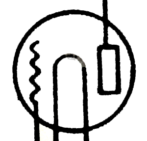
In Figure 1 there is a progression from the diode to a two plate triode which is the subject of the experiment described below. In the third part of Figure Deforest seems to go off on a tangent inserting what looks like a magnet and something resembling a grid into the tube.In Figure 2 he shows the grid triode but below he again shows the two plate triode. It is clear he must have spent a fair amount of time working with this two plate triode in an attempt to make it work. This probably stems from his lack of understanding of how the triode Audion worked.
Inventors of this period never went directly from point A to point B. Mostly they didn't know where point B was, so they took long detours to points K, Q, X, Y, and Z. Figure 1 appears to be an example of this. Most inventors never admitted to taking these detours, the bigger the ego the less willing they were to admit to it.
Looking into De Forest's personality.
Another inventor named Edwin Armstrong figured out how to use De Forest's Audion to make an oscillator. I think this was about 1916, give or take a year. Deforest sued Armstrong claiming patent infringement. The court battle lasted until 1930 and most experts believe that the court got it wrong in deciding for De Forest. The electrical engineering community refers to the circuit developed by Armstrong as the Armstrong oscillator not the De Forest oscillator. What came out in the trial was that De Forest didn't understand how the Audion worked. Under hours and hours of cross examination he was never able to explain, either on a layman's or technical level, how the Audion worked. Also historians have reported that his ego was legendary.Now here is what used to be a leap of speculation but now is shown to be true. De Forest made a bulb* with a filament and a plate with which he duplicated the experiments of Edison and Fleming. Since he didn't understand how things worked he would have been shooting in the dark. He didn't have a clue where point B was and apparently he never knew. He just stumbled around until he hit it by chance. He made a bulb with a filament and two plates. The diagram above shows exactly that device.
Experimenting with such a device he got some effect. He would have tried moving the plates around and likely found that the relative positions of the two plates and filament drastically altered the effect. He even played with magnets. Somewhere along the line he turned the other plate into a zigzag wire and placed it between the filament and plate.
* In writings from that time which I found on the web officials of De Forests company referred to the devices as Audion bulbs.
It is clear that the first vacuum triodes did not have the control element located between the filament and plate but on the opposite side of the filament from the plate. I have a 1930 issue of the Radio Amateur's Handbook in which some of the tube schematic symbols are drawn with the grid on the opposite side of the filament from the plate as shown here. This is likely a hangover from the very first triodes.

For a verbal description click here.
As the patent dates above indicate, it didn't take De Forest long to make the grid into a grid and place it where it logically belonged, between the filament and plate. He thought that some residual gas should be left in the tube. Engineers at RCA discovered that a high vacuum made the tube work much better.One thing I learned in researching on the web was they had to make a bunch of bulbs, as they called them, and then test them to see what they had made. Every individual was different. This was also true of the early transistors. Surprised?
STOP THE PRESSES AGAIN.
I have received an email from a gentleman named Wolfgang Holtmann who is a ham with the call sign PA 0 FTF. He has also experimented with a triode made up of a cathode and two plates. It seems the 6AX5 rectifier has the perfect geometry for this experiment. You can read some very interesting material at the following link.It is gratifying to know I am not alone in this somewhat off the beaten track area of interest.
A "Modern" Audion Tube.
To duplicate De Forest's experiments we need a tube with two plates and one filament or cathode. Looking at schematic symbols can be deceiving. Almost any full wave rectifier looks like that in its symbol. But most are not. Fortunately for us one is. It is the 6AX5. It uses an indirectly heated cathode and has the two plates placed one on each side of it with an opening between. Here is a photograph to prove it.

For a verbal description click here.
The blurry picture is gone. Someday has arrived and I have a wonderful camera made by Kodak. It definitely takes a better picture. The white rod in the center is the cathode and the two dark objects are the two plates. As far as I know this is the only tube that is made this way. Antique Electronic Supply has them for $4,75.What to do
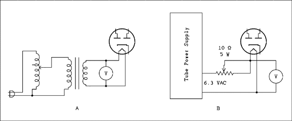
First of all De Forest was working with devices that were little more than light bulbs. Their filaments didn't emit electrons nearly as efficiently as modern tube cathodes. Just at the time when tubes were perfected they went out of style. The 6AX5 cathode is much too efficient for our purposes so we have to do something about it. We have to operate the heater from a very low voltage. I found the optimum voltage to be about 1.6 volts. I only had two tubes to work with so, as the saying goes "your mileage may vary". So the first thing you need is a way to lower the heater voltage. Below are two methods. Figure A uses a Variac in the primary of a 6.3 volt filament transformer. Figure B uses a pot connected as a rheostat in series with the heater. You need a 10 ohm 5 watt pot. The optimum voltage is somewhat critical. A change of a tenth of a volt makes the difference between working and not working. More about this later.

For a verbal description click here.
The Audion Detector Circuit
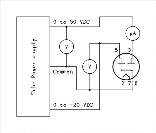
Someone is likely to point out that better reception can be obtained just by using the rectifier tube as a diode detector. OF COARSE YOU COULD! But that's not the point. As this is being written the 100th anniversary of the first powered airplane flight is approaching. Several groups have built duplicates of the original Write flyer and are planning to fly them on the anniversary date. They could fly much farther in much more safety and comfort in a Cessna or Piper. But that's not the point. Just as those intrepid modern day flyers want to walk in the footsteps of the Wright brothers you can walk in the steps of Lee De Forest just as I did as I performed the experimentation for this article.First of all neither element in the tube is a grid. So I will call the elements the cathode, the control plate, and the collecting plate. The first thing I tried was a DC characteristic using the circuit below. The results were less than encouraging.

For a verbal description click here.
After some optimization of the heater voltage the best I could do was a change from 116 microamps to 66 microamps for a change in control plate voltage of 0 to -20 volts. That wasn't very encouraging. A family of curves known as a plate characteristic is shown below.

For a verbal description click here.
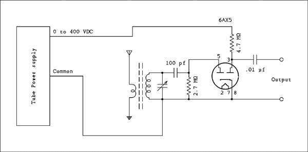
Next I tried injecting some AC at the control plate with a 4.7 Meg ohm resistor in the collecting plate and a supply voltage of 400 volts. I found that with A little positive bias on the control plate it would produce full wave rectification. Interesting but probably too low an impedance to be useful.Finally I decided to connect a tuned circuit and an antenna to see what it would do. Here is the circuit.

For a verbal description click here.
The coil is a ferrite rod antenna taken from a junked AA5. (Elsewhere on this site I believe I said that I have never seen a tube radio using a ferrite antenna. Well, now I have.) The antenna winding is 9 turns of insulated wire wound on the end closest to the cold (grounded) end of the main coil but not over the coil if you can help it. The capacitor is one from the same junked AA5. Use the large section. As with the crystal set the earth ground is necessary for operation. The green grounding post on a power supply that is equipped with a 3 wire line plug and cord will work well. You may want to be really authentic and drive a copper plated steel rod into the earth. If you wound your own coil for the crystal set you can use that coil and capacitor combination if you like.Operating the Circuit
Set the power supply voltage to 400 volts. Connect the output terminals to the input of an audio amplifier such as a tube Hi Fi amplifier. Do not use a solid state one as it could be damaged by high voltage spikes from this circuit.With such a low voltage on the heater the tube takes a long time to warm up. You may begin to hear something about 1 and a half minutes after applying power to the heater. It takes an additional 30 seconds for the sound to come up to its normal operating level. You can shorten this time by giving it about 3 volts for 15 seconds then cutting it back down to 1.6 volts. When you make small changes in the voltage it will take several tens of seconds for the cathode to stabilize at the new temperature. Initially adjust the heater voltage for a collecting plate voltage of 20 volts as measured with a 10 Meg ohm input VTVM or DMM. or 30 volts as measured with a 100 Meg ohm VTVM. Then remove the voltmeter and optimize the heater voltage by ear.
Although my expectations were quite low I was pleasantly surprised. I think what made it work so well was the fact that the control plate is connected to the top of the RF coil instead of being connected to a link winding. This is a very high impedance tube both on its input and output. I think I remember reading that somewhere. Using my attic antenna the local stations will produce about a volt of carrier across the tuned circuit.
There was some audible distortion in the audio signal. The sound was somewhat clearer if the 100 pf capacitor and 2.7 Meg ohm resistor were omitted and the top of the tuned circuit tied directly to the control plate. However, the sensitivity was also reduced. This is something for you to experiment with. Are these really the best values? I just copied them from the grid leak detector. I believe that detection is taking place between the control plate and cathode.
Now here is the problem. The way this tube behaves flies in the face of logic. Remember the geometry. The two plates are across from each other with the cathode in the middle. When one of the plates is made more negative it should repel electrons toward the other plate. Making the control plate more negative ought to increase the collecting plate current but it does not. The control plate acts the way a grid would. The effect is admittedly small but definite. If anyone can figure out why it acts the way it does I will place your solution here with your name in large letters. What did you expect, money?
I have read stories that indicated the placement of a magnet near the tube would soup up it's gain. My own experiments with a magnet showed just the opposite effect but I don't have a horseshoe magnet which was what was indicated would work. Maybe you have one? There's something else you can experiment with.
A representative of De Forest's company writing at the time stated that a magnet did not offer any beneficial effect and the strong field could damage the elements inside the bulb. I doubt there is any similar concern with the tube used in this experiment.
That seems to be all their is to say. Have fun and remember you are walking in some large footprints.
Thank you for visiting my page at Angelfire.
Please come back and visit again!
This site begun March 14, 2001
This page last updated September 28, 2010.