
Although design and marketing of ham radio equipment was put on hold during WW II Research and development on HF and VHF transmitters and receivers was accelerated. After the war all that new development became available once more to hams and ham equipment manufacturers. The result was a leap forward that didn't subside until sometime in the 1960s. I delt with third and fourth hand prewar receivers until 1958 when I saved up enough money to buy a National NC 300. That was my introduction to quality signal reception and there was no going back.Typical Ham Band Receivers From About 1957.
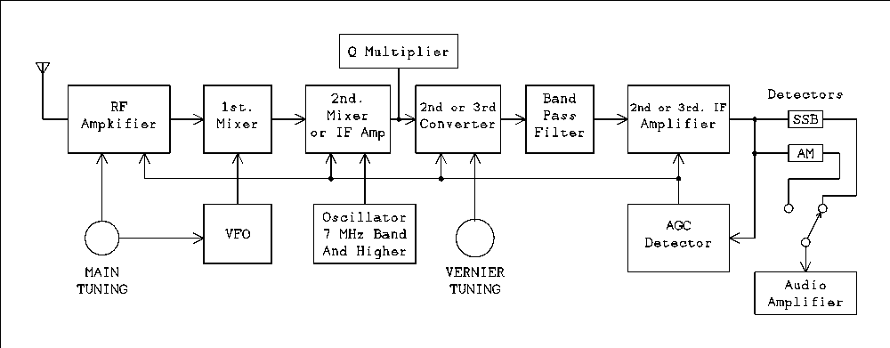
Below is the block diagram that fits the two classical ham band receivers Hallicrafters SX 101, and National NC 300. Only the intermediate frequencies were changed to protect the engineers. The SX 101 and also the SX 100 (general coverage version) used a first IF of 1650 kHz and a second IF of 50.5 kHz. The NC300 and its updated version the NC 303 used a first IF of 2215 kHz and a second IF of 80 kHz.
Oh, by the way, the difference between a mixer and a converter is; a mixer consists of two tubes, mixer and oscillator, while a converter is a single tube with 5 grids which performs both functions of oscillator and mixer. Don't be confused by a dual tube such as the 6U8. In this and similar tubes the triode is often the oscillator and the pentode is the mixer. These are separate tubes which just happen to be enclosed in the same glass envelope. True converters are tubes such as the 6BE6 which has only one cathode, 5 grids, and one plate and serves as both oscillator and mixer within the one tube.
You will note in the classical receiver AGC is not applied to the mixer. AGC can lead to pulling of the oscillator frequency on the highest bands. Also separate mixer and oscillator tubes are used for the first conversion also because of oscillator pulling. Even if AGC is not applied to a pentagrid converter a strong signal can alter the plate current enough to pull the oscillator frequency.
You will note that the crystal filter is inserted in the first IF between the first mixer and second converter. I think this is because a crystal for the frequencies of 50 or 80 kHz would be quite large. Also I think the filtering would be just too sharp and would be too much of a good thing. Also, as far as I know, amplifiers in the first IF are never used. Although converters and mixers don't have quite as much gain as amplifiers they do have a considerable amount.
The SX 101 used a crystal controlled oscillator for the second converter. I think this was done more for bragging rights than any other reason. True it did not have to be adjusted at the alignment station on the production line. The NC300 used an LC oscillator for the second conversion. I'm sure their thinking was that the tunable first conversion oscillator would be less stable than the fixed tuned second conversion oscillator and so its drift would never be noticed.
Although the band pass filter and second IF amplifier have been shown as separate blocks the filter was distributed as coupled circuits before, between, and after the two IF amplifier tubes.
The Hammarlund HQ170.
Hammarlund borrowed a trick from the National HRO60 receiver. It was double conversion on the 160 and 80 meter bands and triple conversion on 40 meters and all higher frequency bands. Not only that but the 6 meter band was standard equipment.
On 160 and 80 meters the first IF was 455 kHz and the second IF was 60 kHz. On all higher frequencies the first IF was 3035 kHz, the second IF was 455 kHz and the third IF was 60 kHz. On the two lowest frequency bands the second conversion oscillator was simply turned off and the mixer became an amplifier. The tuned circuits in the plate of the first mixer had to be switched according to what band was selected.
Instead of a crystal filter the HQ170 used a Q multiplier in the 455 kHz IF. Signal does not pass through a Q multiplier, only a single cable connects external Q multipliers such as the Heathkit to the receiver. A switch can be set to produce a very large and narrow peak or a very sharp null. The circuit uses positive or negative feedback to produce a peak or a null. The Q multiplier looks like a short circuit in the plate circuit of the 455 kHz amplifier or mixer to produce the null. The frequency width of the short circuit is extremely narrow because of the amplifier's gain. When operating in the peak mode it looks like a negative resistance which effectively reduces the resistive losses to a very small value. If the operator attempts to set the peak too high the circuit will break into oscillation. A Q multiplier works much the same as a crystal filter except that the position of the null or peak is tunable across the IF bandwidth. This is not so for a crystal filter.
The HQ170 has one other interesting feature. The oscillator which does the conversion from 455 kHz to 60 kHz is tunable from the front panel. This is a knob the same size as the main tuning knob and is a fine frequency adjustment for easy and accurate tuning of SSB signals. This is handy on the lower bands but is an absolute necessity on 10 meters where the tuning rate of the main tuning is much higher due to the wide frequency coverage of that band. I suppose the same applies to 6 meters but I have never heard an SSB signal on that band.
Band Switching Troubles.
There is one feature that separates all of the receivers described above from those described below. That is band switching of the oscillator (VFO) coil. When the first local oscillator has to operate at a fixed frequency above the incoming frequency the oscillator inductance has to be switched along with the antenna and RF amplifier coils. In the tunable IF receivers described below the VFO always tunes the same range regardless of the band being tuned.My experience with receivers old and new made me painfully aware of this problem. After I got my novice ticket my first two receivers were a National NC45 and an NC100. Both were 20 years old if they were a day and both had a tendency to make random jumps in frequency. Cleaning the band switch helped a little for a little while but copying CW on a receiver that was prone to jump around in frequency was not a happy situation. My purchase of a new NC300 solved this problem. My two pre WW II receivers had no doubt passed through many hands and had been heavily used. No amount of cleaning can restore a worn out band switch. Allowing the VFO to operate in a fixed frequency range eliminates a major source of instability in the oscillator. Also it doesn't hurt that it can be made to operate in a part of the HF band where it is easy to make stable and high Q inductors.
The Drake and its Successors.
The drake 1A was an odd duck, looking more like an oversized VTVM than a receiver. The drake 2A fixed this problem with an appearance that was unmistakably a receiver. The 2B featured a much improved band pass filter which made it the dream receiver for a whole generation of hams who couldn't afford a Collins S-line.

The basic receiver was a double conversion that tuned 3.5 to 4.1 MHz. The first IF was the standard 455 kHz and the second was 50 kHz. The preselector had to be tuned to the proper band and in the case of 80/75 meters to the proper part of the band. This band covered 40% of the preselector's rotation. That made it a two handed receiver but most hams didn't seem to mind because they were accustomed to adjusting the antenna trimmer as they tuned the main dial. The preselector was just a fancy antenna trimmer.
On 80 meters the first mixer acted as a straight through amplifier because there was no input from the oscillator. On higher bands the 80 meter band was used as a tunable IF and an oscillator using a crystal of the proper frequency was switched on to make a crystal controlled converter.
To tune the 40 meter band the crystal oscillator needs to be 7 MHz away from one end or the other of the 80 meter band. The crystal frequency could be -3.5 MHz in which case the difference frequency would be 3.5 MHz -(-3.5 MHz) = 7 MHz. The high end would be tuned at 4 MHz on the basic receiver so we have 4 MHz -(-3.5MHz) = 7.5 MHz. Negative frequency crystals are about as scarce as hen's teeth. Probably more so.
I am aware that a conventional positive frequency crystal would convert the 40 meter band to the 80 meter band but there would be this huge signal at the bottom of the band which due to overloading of the second converter would probably wipe out the bottom 50 kHz of the 40 meter band.So Drake uses an 11 MHz crystal which gives 11 - 7 = 4 and 11 - 7.5 = 3.5. This turns the 40 meter band upside down giving a frequency decrease for a clockwise rotation of the tuning knob. In fact this was the only thing that reviewers could find wrong with the 2B. For 20 meters he used an 18 MHz crystal which also turns the band upside down. I can't think why he didn't use a 10.5 MHz rock which would have left it right side up. For 15 and the 28.5 to 29.1 part of the 10 meter band can and do use the same crystal (25 MHz). A 12.5 MHz second overtone crystal was used here. Sockets were provided to get the rest of 10 meters but the owner had to buy the crystals.After the 2B.
The Collins S-line, the Heathkit SB-line and the Drake R and T line took a slightly different approach. Instead of using one of the ham bands as the tunable IF they placed it between the ham bands. This way they could avoid the pitfalls of the 2B and make all bands tune in the same direction. This eliminated individual frequency scales for each band and a 0 to 500 scale with the rotary dial with 0 to 100 calibrations and a small slide rule dial with 0 to 5 markings similar to what Collins had been doing since the 75A3 receiver.The Collins S-line used a 200 kHz wide tunable IF which meant they couldn't cover most ham bands with a single crystal. It took more crystals than there were sockets to cover the entire 10 meter band. When the S-line was being manufactured there were, by gentlemen's agreement, AM sections and SSB sections of the bands. You could get sets of crystals for SSB operation or CW operation. The S-line transmitter wasn't capable of AM.
After that ham transceivers, receivers, and transmitters, Went to silicon and became frequency synthesized eliminating the need for crystals for each band.
Up-Conversion.
Up conversion was used in spectrum analyzers made by Hewlett-Packard and some other manufacturers. The advantage of using up conversion was that a wide range of frequencies could be covered without having to switch coils or capacitors in the oscillator. The first generation of HP spectrum analyzers covered from 0 (low audio frequencies) to 100 MHz. If I remember correctly, which is often in doubt at my age, the first IF was 160 MHz. That meant that for a full spectrum scan the local oscillator had to be swept from 160 to 260 MHz. That's a tuning ratio of 1.63 to 1 which is easily doable. This was not a tunable IF system but much closer to the classic fixed IF receivers such as the NC300 discussed above. Although a spectrum analyzer and a communications receiver seem to be very different animals they are closer than you might think. Most spectrum analyzers have built in AM detectors and can be used as receivers by turning off the frequency sweep and tuning them just like a general coverage receiver.So far as I know up-conversion was never used in a commercial vacuum tube receiver. However, that does not prevent ambitious builders from experimenting with the concept. Such a design could either use a fixed frequency first IF and all of the tuning done with the first local oscillator or a tunable IF in which the first conversion oscillator would be crystal controlled. In the fixed IF version the first conversion oscillator would have to be a frequency synthesizer. An analog oscillator operating at frequencies in excess of40 MHz would not have sufficient stability for SSB and CW reception. Such a receiver would have to be hybrid , part silicon and part vacuum tube.
Let's look at a hypothetical up conversion receiver and you'll see what I mean. Suppose our receiver has a block diagram as shown below.

Not indicated on the block diagram are the sharp band-pass filters between converters. They need 3 tuned circuits each having a Q of 100 to ensure that the image rejection is below the noise inherent in the tubes. For our receiver to have a tuning range from VLF (very low frequency) to 30 MHz the synthesized oscillator has to tune from 40 MHz to 70 MHz. That's only a ratio of 1.75 to 1 which means it can be tuned without any capacitor or coil switching. However, I defy you to build an oscillator with analog technology that will tune that range and be stable enough to listen to SSB. The reason the lowest IF is 455 kHz is because mechanical or crystal filters could be used in the 455 kHz IF to obtain the desired selectivity. Or, you could add another conversion to 50 kHz and use an LC filter.
Images.
Say you are listening to a signal at 100 kHz. Your synthesized oscillator will be set to 40.1 MHz. 40.1 MHz - 0.1 MHz = 40 MHz. The image will be at 40.1 MHz + 40 MHz = 80.1 MHz. Somewhere pretty close to the channel 5 audio carrier. Oops? I guess there isn't any such thing as the audio carrier in digital TV. Now suppose we tune to 30 MHz. The oscillator will be set to 70 MHz and the image will be at 40 + 70 = 110 MHz, just above the FM broadcast band which at this writing has not gone completely digital. What I am getting at is that as you tune your receiver the image will tune across some pretty strong signals. Even small broadcast markets have several FM stations running a full gallon.* (110 kW ERP). If you move your IF up to 55 MHz the oscillator tunes from 55 to 85 MHz and the image tunes from 110 to 140 MHz. This part of the spectrum is assigned to aviation and space communications. You are not likely to experience any interference unless you live next door to an airport. You might not have to shield as heavily to avoid picking up signals on the image.* The term full gallon was originally used by hams to denote a transmitter power of 1,000 watts, the legal limit for hams on the HF bands. Subsequently the term has been adopted by other services. For example a full gallon on the AM broadcast band is 50,000 watts, and a full gallon on CB is 5 watts. Hi hi.
Matching Transmitter or Transceiver.
But beware the image leakage from a transceiver or matching transmitter. In a receiver the image signals leak in but in a transmitter the images leak out. A transmitter leaking an image onto a flight control frequency can get you into some big trouble in a great hurry. This could amount to a fine you couldn't afford and jail time to boot. If you are going to use a 55 MHz IF you had better confine yourself to receiving only. If you want to make a transceiver you had better stick to a 40 MHz IF. Your image will not be interfering with anything that can be interpreted as emergency communications.Up-Conversion with Tunable IF.
There was a moment in time, mid 1960s, when tubes were clearly on their way out and transistors were just becoming good enough to be used at radio frequencies up to 100 MHz and maybe a little more. Small scale integration was in limited production and large scale was in the foreseeable future. The concept of the frequency synthesizer was known and had been for several years but wasn't practical at the current state of the art. Enter the HRO-500. I had my hands on one for a few hours and like any good engineer as I tuned it I was figuring out how they must have designed it. It was the same size as any of its vacuum tube predecessors with several heavily shielded modules inside. It was general coverage in 1 MHz bands. There was a small drum dial on one top corner of the front panel with a small tuning knob next to it. The drum had numbers 1, 2, 3, etc, up to, I don't remember how high. Maybe it was 30, maybe it was 50. Next to the dial and knob was a light labeled "Lock". The light came on as each number came into view and went off between numbers. The main tuning dial then tuned from the number of MHzs shown to 1 MHz higher. There was a spurious signal at every integer MHz location. The specifications said it was equivalent to less than 1 micro volt at the antenna connector. Below is the block diagram as I imagined it to be. I have only changed my estimation a little since I formed it some 50 years ago.
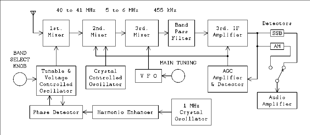
I have no way of knowing what the IFs are so I have just made them up. Information on the internet seems to be quite scarce on this model. A later model, the HRO600, dispensed with the HRO style mechanical dial and used Nixie tubes for the frequency display.
The receiver had no preselector and I think no RF amplifier. To avoid cross modulation of signals in the wide open front end it probably used a diode doubly balanced mixer. An external preselector and RF amplifier was an available accessory. The "Tunable & Voltage Controlled Oscillator was tunable by the small knob described above. At 1 MHz intervals the oscillator would come close enough to one of the harmonics of the 1 MHz oscillator for the phase lock loop to lock in.
The phase lock loop has been known since the earliest days of television. One was used in every TV receiver to synchronize the horizontal sweep with the sync pulses that were part of the composite video signal. It was never called by that name so if you ask a TV service person from that era about it he will tell you there was no such thing. PLLs were also used to detect very weak signals from planetary probes and to keep track of their position to an accuracy of a few meters.The phase detector delivers a DC voltage output that is proportional to the phase difference between the two signals at its inputs. The voltage is zero when the phase difference is 90 degrees, negative when the phase difference is 0 degrees and positive when the phase difference is 180 degrees. When the two frequencies become very close together the voltage is changing at the rate of the difference between the two frequencies. The VCO (voltage controlled oscillator) is wobbled by the voltage and at some point in time will cross over the frequency of the reference frequency from the crystal oscillator. At this instant the VCO becomes locked at a phase difference of 90 degrees and the two frequencies are identical. The VCO will always lock to the harmonic that is nearest to the frequency set by the manual tuning control. When the oscillator is tuned so as to change bands the frequency of the oscillator is moved so far off from the harmonic it was previously locked to that lock is lost. As the oscillator is tuned close to the next harmonic the phase will again lock in setting the frequency to that harmonic.
The oscillator that converts the 40 to 41 MHz range to 5 to 6 MHz could be, and probably was, derived from the 1 MHz crystal oscillator rather than using a separate crystal.
Why Use Up-conversion?
If you want a ham band only receiver using analog tuning there is no need to employ up-conversion. If you want to used digital synthesized tuning you will have to use up-conversion no matter what kind of receiver you want.The Frequency Synthesizer.
The phase lock loop is a sub system of the frequency synthesizer. The frequency from a reference crystal is passed through a programmable frequency divider. It can be set to divide the frequency by any integer within the practical limits and need of the system. The VCO frequency is also divided by a fixed integer and the two frequencies compared in a phase detector to lock the VCO to the divided crystal frequency. In modern transceivers the tuning knob is generating a binary number that programs the frequency divider. The VCO must be capable of being voltage tuned over its entire range without switching any coils or capacitors. Don't even try to imagine doing this with tubes. The fastest Vacuum tube computers never got close to the switching speeds necessary to implement such a system.If you have your heart set on a general coverage HF receiver you can use up conversion employing the block diagram of the HRO500. But you don't have to. Although the HRO500 was discrete transistors it could be implemented with vacuum tubes with little more complication than a conventional general coverage receiver. The advantage to using up-conversion is that you can tune as low as you want to go even down to high audio to listen to lightening static. Doing so with a band switched general coverage receiver gets very clumsy.
Wide Open Front End or Band Pass Filters.
If your local RF environment is devoid of any strong close by transmitters you might get away with a wide open front end. A doubly balanced mixer made of diodes, sometimes called a ring modulator, has a rather wide dynamic range and will not produce cross modulation products if all signals come from far away transmitters. Such a mixer may have a rather high noise figure which will restrict its sensitivity. The moment you add a preamplifier you will also add all kinds of whistles and birdies from cross modulation products unless you also add tuned circuits or band pass filters to restrict the signals the amplifier has to cope with.The design procedure and the filters themselves get more complicated as the percentage bandwidth increases. The AM broadcast band has a percentage bandwidth of 114%, the 80 meter ham band 13%, and the 15 meter band 2.1%. It would probably be easier to implement the AM BC band filter as a 540 kHz high pass filter and a 1700 kHz low pass filter connected in either order. Filter design is most definitely beyond the scope of this article. There is lots of information on the web and some free design programs as well.
Conclusion.
It may seem as if I have wandered away from the main stream of receiver design but I wanted to include material for all levels of receiver builders. The following chapters will include specific circuits for the various subsystems of a communications receiver. Whether you are intending to build a receiver or are just curious about the inner workings I hope you will find some useful information in this article.
Introduction
Image Rejection, IF Bandwidth, and Number of Conversions
Block Diagram. You are here.
Construction Tips
Power Supply
Audio Amplifier
RF Amplifier and Preselector
Converters, Mixers, and Local Oscillators
IF Amplifiers and Band-pass Filters
Detectors
AGC (Automatic Gain Control), and S Meter (Signal Meter)
Thank you for visiting my page at Angelfire.
Please come back and visit again!
This site begun March 14, 2001
This page last updated January 27, 2016.