Communications Receivers.
AGC (Automatic Gain Control).
Can you imagine tuning a receiver that doesn't have AGC (automatic gain control)? AM broadcast radios didn't have it until the early 1930s. Tuning across the dial was a two handed process. One hand on the tuning knob and the other on the volume control. Further more distant stations would undergo drastic changes in received signal strength as the propagation path changed with time. When designers figured out how to add AGC to radios they became more popular with listeners who did not like to sit next to the radio with a hand on the knob. Here is an example of a broadcast radio with AGC.
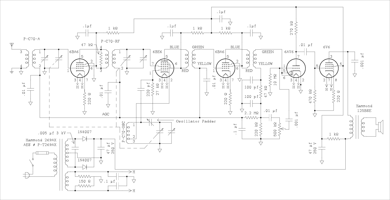
Counting tubes from the left look at the IF transformer between the third and fourth tubes. Coming off the bottom end of the secondary you will see the network consisting of two 100 pf capacitors and a 47 k ohm resistor. Coming off the junction between the 47 k ohm and 220 k ohm resistors you will see a 2.2 megohm resistor and a 0.1 μf capacitor to ground. Follow the line and you will see it is connected to the bottom ends of three transformers which feed the control voltage to three of the tubes. This radio has very good AGC action and local stations are not significantly louder than those a thousand miles away. This is to illustrate how AGC can be derived from the diode detector shown first in the previous article and how it is applied to the RF, converter, and IF, amplifier tubes in a receiver. In a communications receiver AGC would not be applied to a mixer that is driven by an LC tunable oscillator. The changing voltage on the mixer causes the plate current to change which can change the load on the oscillator causing its frequency to change which is referred to as oscillator pulling. A little pulling doesn't matter in a broadcast receiver.
Delayed AGC.
This does not mean delayed in time but its action is delayed until the signal achieves a certain strength. In any receiver the noise that comes into the antenna along with the noise that is generated within the tubes will activate the AGC and desensitize it before it hears the first signal. It would be nice if all amplifiers could be operating at full gain so a very weak signal could be heard when tuned in. There is a way but it requires a separate detector for the AGC. As with anything there are as many ways of doing it as there are engineers in the field but one way is this.

This circuit uses the 6AL5 or can use the much older 6H6 if you prefer. Most 6H6 tubes are in a metal envelope and so are naturally shielded. The left hand diode is the AM detector and works the same as the one in the original AM detector circuit. The right hand diode is the AGC detector and has a positive bias on its cathode to delay the AGC action. If the peak voltage which is coupled by the 100 pf capacitor to the plate of the diode from the IF transformer is less than the voltage on the diode cathode there will be no rectification and no voltage produced by the circuit. When the AC voltage exceeds the cathode bias, rectification begins and a negative voltage appears at the plate of the diode. This voltage is passed to the IF and RF amplifiers to reduce their gains. Some additional filtering will be required to prevent oscillation. The 2.2 megohm resistor discharges the 100 pf capacitor in the absence of a signal.
The ARRL handbook showed two fixed resistors and text accompanying the diagram suggested a delay voltage ranging from 2 to 10 volts. I substituted a pot because as the wide range of voltage suggest this is not a one size fits all situation. The optimum setting for the 80 meter band will be quite different from that for the 10 meter band. I think it would be interesting to make this a front panel control.
Amplified, delayed, and two speed AGC.
If the fast AGC normally used on AM signals is used for SSB reception the sound is most unpleasant and can even be hard to copy. A fast attack slow release time characteristic is needed.

Amplified AGC means that the signal is passed through an additional IF amplifier before signal is taken off and fed to the AGC detector. This circuit is lifted whole from the Drake 2B receiver. The last IF in the 2B is 50 kHz which is considered to be audio by the amplifier building crowd. A simple resistance coupled amplifier is used as the AGC amplifier. It has a calculated gain of 11 by the small signal amplifier equations. If a signal comes in which requires 11 volts of AGC to turn down the gain of the receiver the voltage going to the detectors will have changed by only 1 volt. This really does make signals sound the same whether they come from the ham with a full gallon who lives 2 blocks away or a station at the south pole. The delay is set by the bias on the cathode of the triode which is also the cathode for the diodes.
A band reject filter is used to ensure that no residual 50 kHz signal will be fed back to the grids of the IF amplifier tubes. Because of the nature of the band pass filter used in the 2B the grid of the last IF amplifier must be parallel fed. The AGC voltage receives some additional filtering by the 33 k ohm resistor and 0.001 μf capacitor. The 1 megohm resistor prevents the AGC filter circuit from loading the band pass filter. This AGC voltage will have a very fast attack even when the switch is set to slow. In the fast position the 0.001 μf capacitor to the left of the bias adjust pot is charged through the 680 k ohm resistor. When the signal is removed the capacitor discharges through the other 680 k ohm resistor and the bias pot in series. The discharge will be a bit slower than the charge but not by enough for the ear to detect.
When the switch is set to the slow position a signal will charge the 1 μf capacitor through the 33 k ohm and 15 k ohm resistors in series. The voltage at the junction of the two resistors will rise faster than the voltage directly across the capacitor permitting a faster attack. The voltage applied to the grid of the last IF tube will increase almost as fast as it did when the switch was in the fast position which gives an even faster attack. When the signal ceases the one μf capacitor discharges through the series combination of the 680 k ohm and bias pot. The release time is 100 times longer for the slow position as for the fast position while the attack times are similar enough as to not be annoying to the ear.
S Meters.
An S meter might be thought of as a luxury but I think most hams wouldn't buy a high priced receiver if it didn't have one. The S meter can be as simple or as complicated as desired. It is really nothing more than a DC voltmeter that measures the AGC voltage.You might think that all you need to do is to connect a passive DC voltmeter similar to that found in a VOM across the AGC line and you are all set. If you use a 50 μA meter with a resistor to produce a 25 volt full scale meter the load on the AGC line will be 500 k&Omega:. The Drake AGC circuit above has an output resistance in excess of 680 kΩ when set to the fast position, and about 33 kΩ in the slow position. The additional load of the meter would cause the amount of AGC to change between fast and slow. All in all this is not a happy situation. One possible solution would be to use a cathode follower. This would require a negative bias supply capable of delivering up to 10 mA. The one in the Drake is only good for a few μA.
On the complicated end are circuits that use a twin triode such as a 12AU7 connected in a circuit that is very similar to a VTVM. Such a circuit would have minimal drift and not load the AGC line but it still requires a sturdy negative bias supply.
In the middle is one like the figure below.

In this circuit the IF tube doubles as a DC amplifier for the meter. In order to make this circuit work the IF tube must be biased a little on the low gain side. You may not find this satisfactory. Although the meter is labeled as 1 mA I don't think it could be made to work with a meter of this low sensitivity. A 50 μA or at the highest a 200 μA meter would be needed. The zero adjust pot needs a positive supply of a few volts and rather than burn up a lot of power dropping it from B+ the cathode of the audio output amplifier is a good source. The cathode must be very well bypassed to ground.
The cathode resistor in the IF amplifier should be selected for a voltage drop of 1 or 2 volts with no signal into the receiver. Weather it's 1 or 2 depends on how much gain reduction you feel you can tolerate in this amplifier. If the answer is 2 volts you probably can get away with using a 1 mA meter.
Adjustment, Method 1.
The pot on the right of the meter is the zero adjust and the rheostat to the left of the meter is the calibration control. With the receiver well warmed up set the zero adjust control for a reading at the low end of the meter scale, usually S1. Connect a signal generator and set its output to 50 μv. Adjust the calibration control for a reading of S9. Turn off the signal generator or tune it far away from the test frequency but leave it connected to the receiver antenna connector. Again adjust the zero control. Go back and forth until the adjustments no longer need to be changed.Adjustment, Method 2.
The pot on the right of the meter is the zero adjust and the rheostat to the left of the meter is the calibration control. With the receiver well warmed up set the zero adjust control for a reading at the low end of the meter scale, usually S1. Unplug the tube from its socket and adjust the calibration control for a full scale reading, 40 over 9, 50 over 9 or 60 over 9 whatever scale you are using. Plug the tube back in and allow it to warm up. Again adjust the zero control. Go back and forth until the adjustments no longer need to be changed.Testing?
Although I am not building a receiver as I go just writing these words has made me aware that I have painted myself into a corner with my advice to work backwards. Some product detectors sound better than others and the only way to tell the difference is to listen to a real off the air SSB signal with a real person behind the microphone.You have already shouted to your computer screen "How the hell does he expect me to test an AGC system when I don't have any IF or RF amplifiers to control the gain of". Good question. If you are building a receiver chances are you already have a factory built one. The problem is whether it is based on tubes or silicon. I don't recommend probing around in your expensive frequency synthesized transceiver to find a signal you can pull out for testing a newly built product detector. And there is still the problem of testing the AGC.
If you own one of the classic ham band receivers you might be able to make use of it but only if you are using the same intermediate frequencies. I already have a Drake 2B so I would not be very interested in building a duplicate receiver.
If you have a general coverage receiver you can use it to develop the front end. By tuning it to the IF. Example if you are going to build a tunable IF receiver you could build the crystal controlled or synthesized converter and use your general coverage receiver as the tunable IF for testing. If the first fixed IF is above 540 you can still use your general coverage receiver to test the second converter. But if you are going to use Ifs that are below the AM broadcast band you may be out of luck. You could build an up converter for your receiver. This could also render a ham band only receiver useable for this purpose. Of course the alternative is to forge ahead and build the entire receiver knowing that you have a working power supply and audio amplifier and figure on some troubleshooting of the final product.
Introduction
Image Rejection, IF Bandwidth, and Number of Conversions
Block Diagram
Construction Tips
Power Supply
Audio Amplifier
RF Amplifier and Preselector
Converters, Mixers, and Local Oscillators
IF Amplifiers and Band-pass Filters
Detectors
AGC (Automatic Gain Control), and S Meter (Signal Meter) . You are here.
Thank you for visiting my page at Angelfire.
Please come back and visit again!
This site begun March 14, 2001
This page last updated January 27, 2016.