
Figure 1 LT Spice Startup Screen.
No verbal descriptions.
Before one can teach, one must learn.
I couldn't come as far as fast as I have without this textbook.THE LTSPICE IV SIMULATOR by Gilles Brocard
So far I haven't run into any user interface differences between Version IV and XVII. I suspect most of the changes were internal.
An updated note to my blind friends. Friday, May 06, 2022.
On the surface LT Spice does not appear to be blind friendly. However, because spice started in the days of punched card input and line printer output it still retains a method of text based input and data output. These are explained in the book I am studying to learn LT Spice. I have started on a set of lessons for blind users. Lessons 1 through 5 are now complete and posted.To any other partials who may want to go ahead with LT Spice be warned. Starting LTspice while JAWS is Running will mess up the cursors in LT spice and make it harder to use. Also Jaws must be closed before closing LTspice or the cursors won't be right the next time it is opened. One solution is to close JAWS, start LTspice, and then restart JAWS. If you are partial enough to draw a schematic in LTspice you can start it without JAWS to help you. As a matter of fact JAWS is of limited usefulness when working with LTspice. Another solution is to only run NVDA when using LTspice. NVDA does not interfere with LT Spice so you can run them at the same time.
Getting to LT Spice.
For many years I played with the MicroCap student edition through several versions. That edition was quite crippled and the full version costs 1200 dollars the last time I looked. I had heard of Spice and P-Spice for many years before MicroCap but that program was rather intimidating. Then I began to hear of LT Spice. It was free and I wondered if it was too good to be true. After literally years of hesitation I downloaded it and found that it is indeed the full version and it really is free. You can download it from here. They have versions for Windows 7, 8, and 10, Mac OS X 10.7+ and even for Windows XP. The download buttons are about half way down the page. You do have to accept cookies to get to the links. If you find that disturbing there is probably some way around it.Table of Contents.
Lesson 1: Fundamental Drawing Skills and a Simple Simulation. This page.
Lesson 2: Introduction to Frequency and transient Analysis.
Lesson 3: Configuring LT Spice and more Drawing controls.
Lesson 4: Locating, modifying, and installing vacuum tube models.
Lesson 5: Operating point of vacuum tube circuits. Introduction to stepping and plate curves.
Lesson 6: Finding, installing, and using, potentiometer symbols and models.
Lesson 7: Transient analysis of unregulated power supplies.
Lesson 8: Transient analysis of power supply regulators.
Lesson 9: Transient and frequency analysis of amplifiers with feedback.
Lesson 10: Lossless transformers.
Lesson 11: Making symbols and models.
Lesson 1
Fundamental Drawing Skills and a Simple Simulation.What you will learn in Lesson one. How to:
- Open LT Spice and start a schematic diagram.
- Place components on the drawing board.
- Connect the components with lines (wires).
- Turn the grid dots on and off.
- Label nodes so you can recognize them later.
- Add a ground to your circuit.
- Add a generator to your circuit.
- Enter component values so LT Spice will recognize them.
- Place a spice directive on the schematic.
- Run a simulation and see the results.
Opening LT Spice. Ready, Set, go!
So you have downloaded LT Spice, installed it, and started it up. the initial screen looks like this.
Figure 1 LT Spice Startup Screen.
No verbal descriptions.
Kind of dull isn't it. Click on the button in the upper left corner * that looks like a play button and the screen will change to this.
* No, not here, on the LT Spice screen.
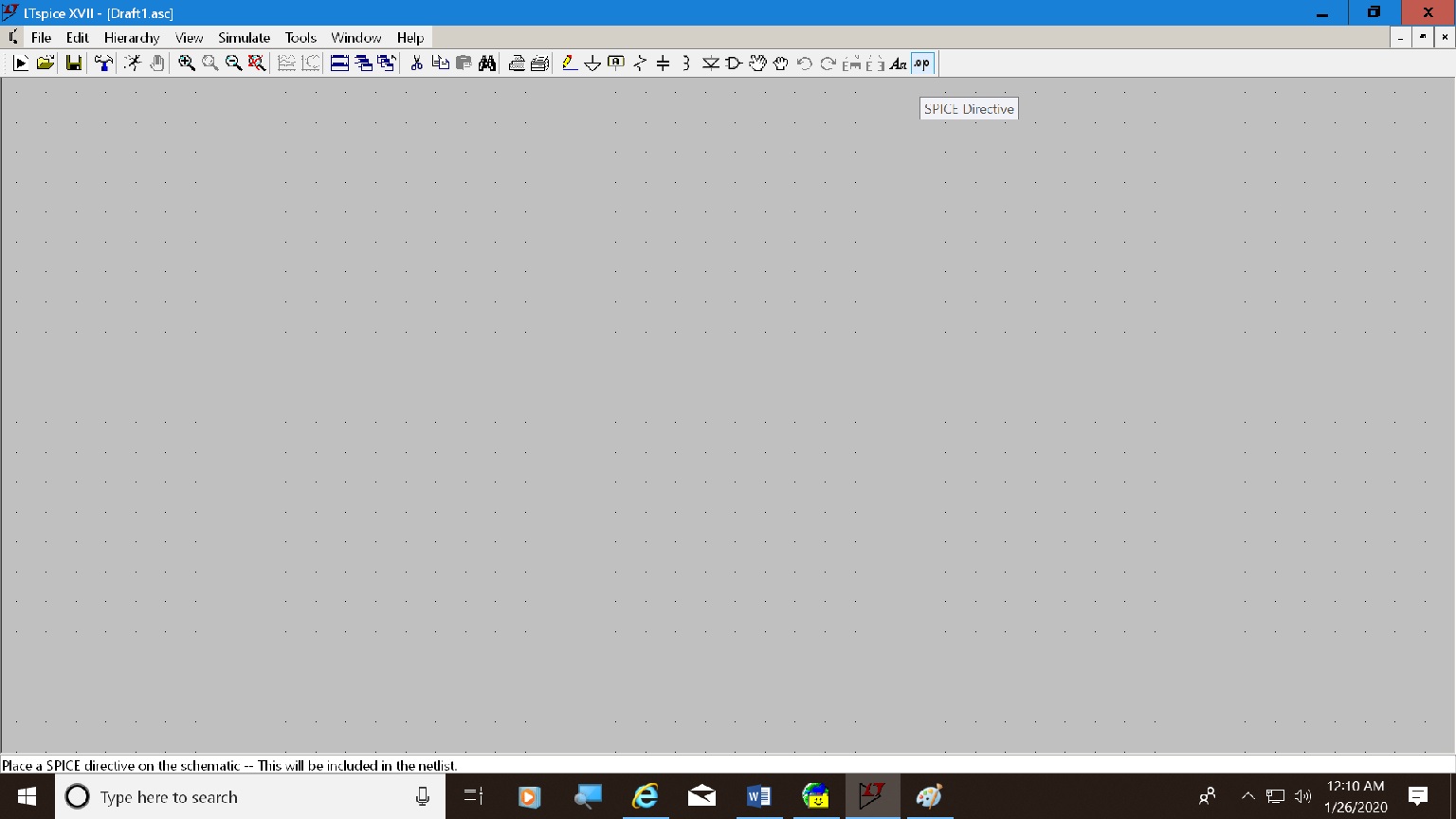
Figure 2 LT Spice Schematic drawing board.
The symbols across the top of the screen may have your eyes rolling but help is available. As you hover over each button with the mouse a description will pop up. I snapped the screen shot while hovering over the .op button. Don't worry, you will learn what is a spice directive soon enough. All of the functions that are on the toolbar are also in the menus. You can use them or the toolbar but I am going to emphasize hotkeys. After you use them for a while they will become second nature and they are so much faster than the mouse. Remember when you were first learning electronics and you struggled to remember ohms law? Now you don't even have to think about it. When you need it it's just there. That's the way LT Spice hotkeys will be if you stick with it.Placing Components on the Drawing Board. Your First Circuit.
Switch to spice and move the cursor to roughly the center of the screen. Press the R (resistor) key with no modifier key. A resistor will appear on the screen. It will be vertical but we want it to be horizontal. Press ctl-R and it will rotate 90 degrees. Left click your mouse and move the cursor a little. You will see this. An unmodified R key always brings up a resistor. Ctrl-R always rotates any component that is held by the mouse.

Figure 3 Showing One Resistor Fixed in place and a second that moves with the mouse.
Right click to get rid of the second resistor.Type the letter C (capacitor) and move the cursor. You will see that it has turned into a capacitor. Position it to the right of and below the resistor. Left click then move the mouse a little. Right click to get rid of the second capacitor. We want the capacitor to be vertical.
Turning the Grid Dots on and off.
Notice on my screens there are rows of little dots forming a grid pattern. If there are no dots on yours press ctrl-G. This key combination toggles the grid dots on and off.Drawing Lines (wires).
Now press F3. The cross cursor will turn into a dashed line cursor that extends from left to right and bottom to top of the drawing board. You are now ready to draw connecting wires between the parts. Set the cursor over the right end of the resistor and left click. Move the cursor to the right and you will see that you are drawing a line. Play with it a bit by moving the cursor all around. Note that the line always draws horizontal or vertical. There is an option you can change to allow diagonal lines but we are getting ahead of ourselves. Position the cursor so its horizontal line goes through the resistor and its vertical line goes through the capacitor, then left click. Now move the cursor down until it is over the end of the capacitor and left click again. The resistor and capacitor are now connected. Move the cursor away and you will see that no line is being drawn.Position the cursor over the corner of the line (wire) and left click. Move the cursor 4 dots to the right and left click again. Move the cursor up a little and right click. Notice that the line that was drawn between left clicks remained on the drawing while the one that was drawn between a left click and a right click disappeared. You are now out of line draw mode but you can get back in by pressing F3 again.
Naming Nodes (connection points).
Electrical engineers refer to a point where two or more components connect together as a Node. They are assigned numbers in spice but the only way to see them is to open the net list. Spice old timers will know what a net list is and how to interpret it. (BTW. If you are an old timer why are you reading this page? No criticism meant, just wondering.) Unlike Microcap, LT Spice does not provide a way to show node numbers on the schematic. If you need to identify a node or set of nodes later you must give it a name.assigning names to specific nodes.
Press F4. This is what you will see.

Figure 4 Showing Net Name which is how you can name any node. More on this later.
Place the typing cursor in the long text box and type the word "out". You can type it with an upper case O, all cap, or all lower case. It doesn't matter because this is a name you are going to assign to a node. You could even call it output or something weird if the fancy strikes you.

Figure 5 Showing what you see after clicking OK.
Click the OK button. You now can see the word "OUT". The word and the little blue square underneath it will move with the mouse. Position the blue square over the end of the line that comes out from the corner of the line that joins the resistor and capacitor and left click. Move the mouse a little and right click to free the mouse of the second instance of the label. You will see the word "OUT" move to appear at the end of the line.Exercise 1
Adding a Ground Symbol.
If you forget to add a ground, your circuit won't run. Spice demands a ground for all circuits.Complete the drawing by adding the bottom line and ground symbol. One way to call up the ground is obtained by pressing G. The ground symbol does not come with a long lead. You must draw a line downward a little to keep the symbol from looking crowded against the bottom line.
Adding a Generator.
Like any real circuit if you want to test it you need some way of giving it a signal to work on. On the bench you connect it to a signal generator. So what do you think we do in Spice? We hook it to a signal generator.Select Component Symbol, F2.
This is also invoked by selecting the and gate symbol from the toolbar. You will notice that the heading is select component symbol, not select component. Some of the items you will find in this menu have a model to go with them such as the voltage source you just placed on the schematic, and as you will find, some don't such as the vacuum tubes. When you need to know how I will show you how to call up a model.The difference between a symbol and a model is a symbol is just the representation of a component on the schematic drawing board. There is nothing about the symbol that tells spice how to calculate its response to different electrical conditions. The thing that tells spice how to compute responses is called a model. As it happens the voltage source comes with a model but some entries in the list do not and one must be supplied by the user.Place the generator on the schematic as shown below and connect it with wires.

Figure 6 Showing the retrieval of a generator.

Figure 7 Showing the placement of a generator on the Schematic drawing board.
Entering component values.
Do you think the diagram is complete? Think again. Spice needs specific values for all components before it can do a thing.
Right click on the generator. Set the DC value to 10 volts and don't worry about the rest. Click OK or press enter.
Right click on the resistor. Set the value that is now R to 1k. Be sure to type 1k without a space between. It really doesn't matter whether you type a capitol K or a lower case k. It's all the same to spice. Click OK or press enter.
Right click on the capacitor. Set the value to 0.15u or .15u. Once again its all the same to spice.
Whatever you do don't put in any spaces or leave off the u. Omitting the u will result in a .15 farad capacitor. Spice doesn't know that's an unusually large value. It doesn't know anything. It's just a stupid program that does exactly what you tell it to do instead of doing what you want it to do. BTW, it's alright if you enter uf for microfarads, pf for pico farads, but I usually don't. And something else. To enter millions of ohms or millions of hertz you enter 2.2 Meg or 10 Meg. For 1/1000 of ohms you enter m. Now here's the rub. No doubt you are accustomed to entering a capitol M for meg and a lower case m for milli. However, LT spice is not case sensitive. It doesn't recognize the difference between mh and Mh. They are both milli henrys. If you find a mega henry coil it is labeled as Megh or megh. It won't matter. However for clarity to myself I always use a lower case m for milli and a capitol M on Meg for mega. At least that keeps me from getting confused.So now the diagram is complete? Sure looks complete.

Figure 8 Showing Schematic with component values.
The trouble is Spice can't read our minds or our lips. It's not HAL. What do we want it to do? The things you are most likely to do with it are DC operating point, Transient analysis, and frequency response. And how do we tell it what to do? We just type it on the schematic. Let's do the DC operating point.Spice Directive.
Press the letter S on the keyboard and type .op just like that. The op command has no parameters so that's all there is to it.

Figure 9 Showing the Spice Directive Box.
After clicking OK or pressing enter, The directive .op will move with the mouse. Position it where you want it on the schematic and left click.

Figure 10 Showing Placement of a Spice Directive on the schematic.
You can place directives where ever you want to but be consistent so they are easy to find later. I always put them at the top of the drawing.Running the Simulation.
Click on the little running man button to run the analysis.

Figure 11 Showing Results of Operating Point Analysis.
This is obvious but more complex circuits will not be as easy. Node 1 is where the generator connects to the resistor. It shows 10 volts as expected. Node 2 has been renamed, by us, as OUT. It is also shown as 10 volts. The ground is always node zero and is the reference for all voltages so by definition is at zero volts.DON'T FORGET TO SAVE THE DRAWING. I suggest the name Lesson 1.
If you can honestly checkoff each item on the list under the heading "What you will learn in lesson 1", you can go on to lesson 2, assuming I have written it by then.
Back To Table of Contents.
This page last updated May 6, 2022. Home.