


This amplifier has a legendary status among guitarists. Mostly driven by the Jimmy Page connection and mystery surrounding the means to achieve the tone captured on the first two Led Zepplin albums. These amps were made by the Chicago based contact manufacturing house Valco. Valco also made other consumer electronics goods along with their offering of instrument amplifiers. Valco made their own line of amplifiers as well as private labeled offerings for Wards/Airline, Gretsch, National, Oahu, Harmony, Penncrest and Supro.
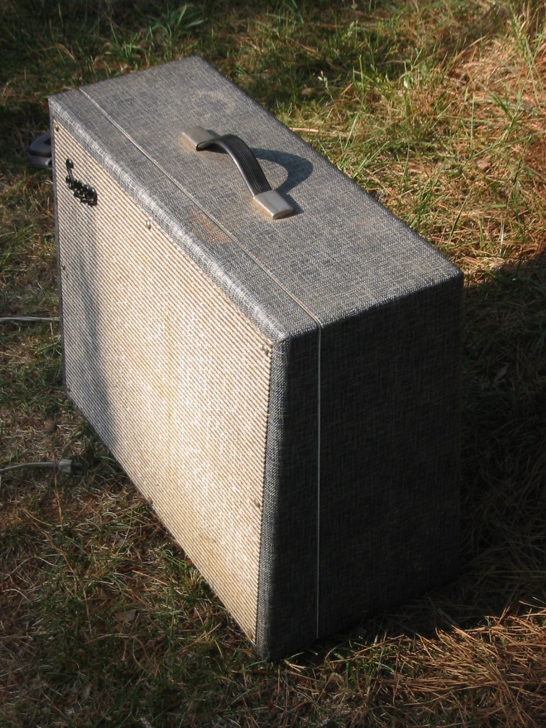
Introduced in late 1964, the Thunderbolt was intended as a bass amplifier for the Jazz player. As such, it was not a good design. The baffleboard was thin and allowed too much speaker movement softening the sound. The tube rectified model also suffered power supply sage which contributed to a lack of punch. As the music of the day was moving toward a more percussive bass sound, the Thunderbolt was panned by bass players. The Thunderbolt featured a simplistic two knob control layout, (one volume and one tone) two 12AX7'S and a pair of 6L6 output tubes. The 1964 and 1965 models were covered in the gray colored "Rhino Hide" materal shown on the example to the right. This covering was listed as "Midnight Blue Vinyl" in the advertising literature. These grey models are typically fitted with a 5U4 rectifier. In 1966, Supro introduced the black tolex-like covering along with other changes. Both the tube rectified and solid state models featured the sporty white stripe that went around the outside of the cabinet. Thunderbolts began shipping with a solid state (diode bridge) rectifier sometime in mid 1966. The solid state rectifier was likely added to reduce power supply sag and crispen up the amp. The move to a solid state rectifier was accompanied with changes to the baffle board design. These changes were added to address complaints from Bass players who never really liked the amp. The power transformers used in the tube rectified and solid state models are not interchangable. The power transformer of the solid state rectified model cannot be used as a replacement for the vacuum rectified model. The solid state model transformer lacks the 5.0 Vac winding for the vacuum rectifier heater and the high voltage winding does not have a center tap. Both model types use the same output transformer. All S6420's were fitted with a 15" Jensen Special Design speaker. The speaker was driven by a pair of 6L6GB or 6L6GC power tubes in a cathode biased arrangement. The 5881 power tube can also be used.
In late 1966 or early 1967 the S6420 model was discontinued.
In 1967 the Thunderbolt name was attached to a model numbered as S6920. The S6920 was very much different from the S6420. The 6920 was in a tall, skinny cabinet with a forward facing turquoise control panel and two knob (Bass, Treble) tone control.
There are a few other Valco made amplifiers that are the same or very similar to the S6420 Thunderbolt:
The original power transformers supplied to Valco were made by Triwec and carried one of these three part numbers: 330-3738, E-3738 or E-3738A.
The output transformer was also supplied by Triwec and carried four (or more) part numbers: 3778, T-3778, E-3778A and 340-3778.
Magnetic Components Inc., who operates www.classictone.net apparently is a decendant of Triwec and has started offering original spec vacuum rectified power transfomers as well as the output transformer which was used on both models. The power transformer is their part number 40-18060, and the output transformer number is 40-18061.
This power transformer has a center tapped secondary rated 700VAC @ 125mA, the filament winding is center tapped and is rated 6.3Vac @ 3.4A, the heater winding is rated 5.0Vac @ 3A.
I have not been able to identify a source for a original appearance reproduction chassis. This is unfortunate as the chrome finish of the originals is often rusted and in fair to poor condition.
The originally supplied speaker is a 15" Jensen C15PS.
A replacement candidate is the Weber 15F150B. Again from Weber (from the product description.) "For tweed Pro and other amps with 15", replaces Chicago Jensen C15P and Eminence 15's. 15", 40oz ceramic magnet, 30 or 50 watts, 1-1/2" voice coil, ribbed cone. This speaker is very similar to the original Chicago C15P. Players who want to get more power tube distortion at a lower volume prefer the C15P over the C15N due to its lower sensitivity. I have to agree on that. You can get a great crunch out of this speaker at lower volumes, yet it has decent dynamics and headroom due to the ceramic magnet. Medium breakup, crunch and punch. Earlier breakup than a C15N, more focused in the mids and upper mids."
The C15PS was used in several other amps, especially the Valco made products. These include the Univox U305R, The National Newport 97 and Alamo Fury 2566.
The S6420 was constructed in a chromed bent steel chassis using mainly point to point construction. There is no tag board as one would find in Fenders or Gibsons of the day. As the circuit is very simple, this is not a real problem.
 The tubes are (from left to right) 12AX7 12AX7 6L6GC 6L6GC with the 5U4 hiding in back next to the FP type capacitor. The sharp observer will note that this example is of the solid state rectified model as the 5U4 is not fitted to the chassis.
The output transformer is mounted on the inside of chassis. The four mounting screws are visible in a square in front of the RCA jack going to the speaker. One of the wooden braces that are used to support the chassis is visible at the left hand side of the chassis.

The wooden braces that are installed to help support the folded steel chassis are readily visible in these pictures. The best I can determine, the chassis wiring in this example is factory original. Note the point to point scrambled path layout. You can also see the simplicity of the circuit in the amp. These pictures are from the interior of a solid state rectified amplifier.
The nine pin socket to the right is the one containing the 12AX7 that has the "spare" triode.
Note the stamped steel bracket mounted around the input jacks in an effort to shield the inputs from interference.
Larger Image

The 200 ohm cathode resistor is visible in the left third of the picture. The resistor is tied to the FP can capacitor lug. Also visible is the 20uF capacitor that is usually added to the interior of the chassis.
The output transformer is shown in right side of the picture. The RCA jack used as the output connection is just above the output transformer.
Larger Image
 A view of the cab with speaker and chassis removed. This shows the '+' pattern in the speaker cutout. This may act as a beam blocker, reducing the highs focused in front of the speaker and contributing to the sound quality of the amp.

