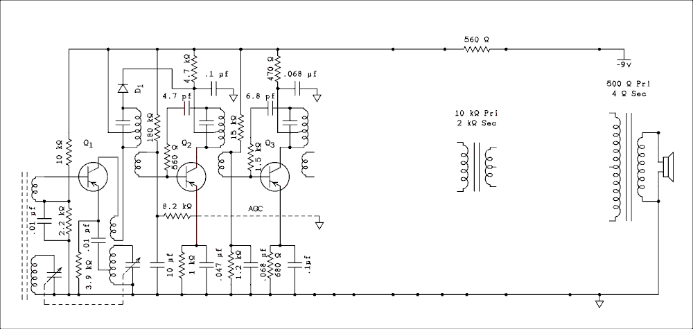
Voxson Model 762 Converter and IF Sections.
For a verbal description click here.
The All Japanese Six Radio.
The IF (Intermediate Frequency) Amplifier.
The first transistor in an All Japanese Six converts the frequency of the incoming station to the Intermediate Frequency (IF). After the conversion two transistors amplify the signal. This is where most of the gain and selectivity take place. Note that there are 3 tuned circuits in the IF amplifier as compared to 4 in the tube AA5 but it seems to be enough.Here are partial diagrams of the two AJ 6 radios we are studying as of this lesson.

Voxson Model 762 Converter and IF Sections.
For a verbal description click here.

Sanyo Super-Six Converter and IF Sections.
For a verbal description click here.
The oscillator coil and IF transformers look like this.

For a verbal description click here.
The red core is the oscillator coil and the yellow, white, and black cores indicate the input, interstage, and output IF transformers respectively.In the Voxson radio Q2 is biased by a 180 k ohm resistor from the top end of the base winding on the first IF transformer to the minus nine volt line, and an 8.2 k ohm resistor from the base winding to the AGC line. Under no signal conditions the AGC line is very nearly at ground potential which accounts for the dashed line to a ground symbol. The base winding is bypassed to ground by a 10 uf capacitor to ensure that none of the audio signal controls the gain of the IF amplifier. If this should be allowed to happen the audio modulation on the signal would be controlled out and there wouldn't be much audio to hear. There is a 1 k ohm resistor from emitter to ground and it is bypassed by a 0.1 uf capacitor.
The base of Q3 is biased by 15 k ohm and 1.2 k ohm resistors. The junction of them is bypassed to ground by a 0.068 uf capacitor. The emitter current is set by a 680 ohm resistor which is bypassed by a 0.1 uf capacitor.
The mid-tap of the interstage IF transformer, the one between Q2 and Q3 is bypassed to ground by a 0.1 uf capacitor and decoupled from the -9 volt line by a 4.7 k ohm resistor. We shall return to this point in a moment. The mid-tap of the output IF transformer is bypassed to ground by a 0.068 uf capacitor and decoupled from the -9 volt line by a 470 ohm resistor.
The diode which is connected between the top of the input IF transformer and the mid-tap of the interstage IF transformer is somewhat of a mystery. It might be some kind of AGC but it is difficult to imagine how it works considering that the diode is connected to the top of the resonant winding of the input IF transformer which is a very high impedance point. The diode's cathode connects to one end of a 4.7 k ohm resistor with the other end going to the -9 volt line. This is a relatively low impedance point. Perhaps I will have an opportunity to build and test this circuit.
The transistor is a triode device and with tuned circuits in both the base and collector the collector to base capacitance is enough to make an oscillator. Note, although the base winding of the IF transformers is not tuned it is tightly coupled to the primary winding, unlike tube IF transformers where the coupling is very loose, so oscillation is quite possible and likely. End of note. Q2 and Q3 are neutralized by a capacitor of a few picofarads in series with a resistor of a few hundred ohms. This causes a voltage that is 180 degrees out of phase with the voltage that is fed back by the collector to base capacitance which cancels the fed back signal and prevents oscillation.
This is the first radio I have ever seen that uses resistors in series with the neutralizing capacitors. In early transistors the collector to base feedback was called the reverse voltage transfer ratio. This consisted of the collector to base capacitance and a real part that was caused by the electric field from collector to emitter that effected the forward drop of the base to emitter junction. Evidently the resistor is meant to neutralize the in-phase (real) part of the reverse voltage transfer ratio. I suspect this was a bit of overdesign on the part of the engineers.
In the Sanyo circuit there are only capacitors in the neutralizing loop. Also there is no decoupling from the -9 volt line to the mid-taps of the interstage and output IF transformers. The base of Q2 is biased in the normal way by 90 k ohm and 18 k ohm resistors. AGC is applied to the junction of the two resistors. A 10 uf capacitor filters the AGC voltage the same as above. The emitter of Q2 goes to ground through the parallel combination of a 2.2 k ohm resistor and a 10 uf capacitor. The base of Q3 is biased from the emitter of Q2 which saves a couple of resistors and a capacitor. Not only that it applies AGC voltage to the base of Q3 which is not done in the Voxson circuit. Q2 acts as an emitter follower DC amplifier to pass the DC level at its base on to the base of Q3. The AGC action in the Sanyo should be much better than that in the Voxson.
General Information.
The Converter.
The IF (Intermediate Frequency) Amplifier.
The Detector and AGC/AVC (Automatic Gain Control/Automatic Volume Control).
The Audio Amplifier Section.
Conclusion.
This page last updated April 25, 2011.