Voxson Model 762 Converter, IF, and detector, Sections.
For a verbal description click here.
The All Japanese Six Radio.
The Detector and AGC System.
The first transistor in an All Japanese Six converts the frequency of the incoming station to the Intermediate Frequency (IF). After the conversion two transistors amplify the signal. The detector recovers the audio that was modulated onto the station's carrier and also a DC level that is proportional to the strength of the incoming signal. The former is passed to the audio amplifier and eventually to the speaker. The latter is used to control the gain of the IF amplifier stage(s) so that strong local stations will only sound slightly louder than more distant ones.Here are partial diagrams of the two AJ 6 radios we are studying as of this lesson.

Voxson Model 762 Converter, IF, and detector, Sections.
For a verbal description click here.

Sanyo Super-Six Converter, IF, and AGC, Sections.
For a verbal description click here.
The detector in the Voxson couldn't be any simpler. The diode D2 rectifies the RF signal from the IF amplifier and recovers the audio from it. For a more detailed discussion of recovering audio from a modulated carrier wave refer to How AM Works.The parallel combination of the 5 k ohm volume control pot and 8.2 k ohm resistor that supplies AGC to Q2, and the 0.025 uf capacitor form the filter to remove the 455 kHz component from the audio. One problem is that calculations show that the audio would begin to roll-off at about 2 kHz which is too low even for a pocket transistor radio. More likely the capacitor is supposed to be labeled 0.0025 uf. You can't always take schematics as the gospel truth. This filtering leaves only audio signal currents flowing in the volume control which are passed to the audio amplifier.
There is a positive DC voltage appearing across the volume pot which is also applied to the 8.2 k ohm resistor which is part of the biasing network for Q2. The 8.2 k ohm resistor and 10 uf capacitor work together to filter the AGC voltage so that no audio is applied to the base of Q2.
The base of Q2 is at a potential of -0.39 volts under no signal conditions. The emitter will be at -0.29 volts which gives an emitter current of 0.29 mA. As the opposite end of the 8.2 k ohm resistor is made positive the voltage at the base will become less negative which reduces the emitter current and also the collector current. This in turn decreases the gain of the Q2 stage. The stronger the station's signal the more positive the voltage at the right end of the 8.2 k ohm resistor will be and the lower the gain of Q2 will be.
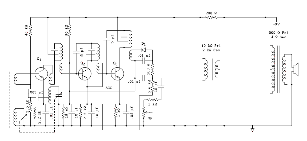
The detector in the Sanyo radio is a bit more complex. Instead of being grounded the lower end of the IF transformer secondary is connected to the AGC line. At the other end of this line there is a 10 uf capacitor to ground which keeps this line at AC and RF ground. The detector diode D1 is reversed from the Voxson radio. The detected signal is filtered by the 0.01 uf capacitor, the 200 ohm resistor and another 0.01 uf capacitor. Both capacitors are returned to the lower end of the secondary coil.
The audio signal is available at the junction of the 200 ohm and 5.6 k ohm resistors. It is taken off by a 10 uf capacitor which blocks the DC and feeds the audio to the volume control pot which is labeled VR in the original schematic but has no entry in the parts list. The 10 uf capacitor prevents DC from flowing in the volume control which reduces crackling noises when the control is rotated.
The AGC system is based on the detector being entirely floating for DC and being a source of DC between its terminals. The positive terminal is the bottom end of the IF transformer secondary which is bypassed to ground through a 10 uf capacitor. The negative terminal is the lower end of the 5.6 k ohm resistor which is also bypassed to ground through another 10 uf capacitor. The negative terminal is connected to the emitter of Q2 while the positive terminal is connected to the base biasing network for Q2. The AGC voltage is the difference between these two points not the voltage from either to ground.
As the strength of the station's signal increases the bias on the base-emitter junction of Q2 is made less negative which will decrease the base current and therefore decrease the collector and emitter currents. This will reduce the gain of Q2. But note that the base of Q3 is biased from the emitter of Q2. As the emitter current of Q2 decreases the voltage at the emitter will grow less negative and this change will be passed to the base of Q3. The collector current of Q3 will also be decreased which decreases its gain. In the Voxson radio AGC is applied to Q2 only. In the Sanyo radio both the gains of Q2 and Q3 are controlled. I'm sure this gives a much better AGC action than is possible with only one transistor being controlled.
General Information.
The Converter.
The IF (Intermediate Frequency) Amplifier.
The Detector and AGC/AVC (Automatic Gain Control/Automatic Volume Control).
The Audio Amplifier Section.
Conclusion.
This page last updated April 25, 2011.