Picture 1, Two Different Homemade IF Transformers. See Text Above.
I'll bet you never thought you would see those words on Fun With Tubes. Frankly, neither did I. But circumstances have converged to provide the incentive so I am going to give it a try. And in the back of my mind Yoda is saying, "There is no try. Do, or Do not."When I came to Western Kentucky University in 1968 as the most junior member of the physics department I was assigned to teach what none of the other faculty wanted to teach. Electrical measurements lab and the electronics for scientists course and lab. It was a case of "Please don't throw me in that briar patch". My degrees were in electrical engineering not physics so I felt right at home. Next to my lab room was a stock room that contained some items that must have dated back to the 1930s. One of the things was a device with a crank and a pointer and dial that increased one count with each turn of the crank. One of the older members of the department told me it was a coil winder. There was one part that moved back and forth with every turn. But after a few turns I realized that it wasn't quite every turn. There was a set of gears that cause the rotation rate to be just a little different. I tried winding a coil with it but it quickly turned into a tangled mess. I was told that the only man in the department who knew how it worked had retired a couple of years ago and moved out of the area. He had not left a forwarding address. Remember what year I said it was? The internet had not been invented yet and wouldn't be for another 20 years. I put it back on the shelf where I had found it. A couple of years later the stock room was moved while I was on summer break. The coil winder and many other items that today are considered by me and others to be precious antiques were gone. "Thrown into the dumpster" I was told. I did not have enough seniority to protest and anyway it wouldn't have done any good. It was too late.
Fast forward to late August of 2018. I've been retired for 17 years and the subject of coil winders has hardly crossed my mind since 1970. The sites I looked at where others described winding coils by hand it was indeed by hand. Pi winding, (I don't know why it's called that), was approximated by randomly moving the wire guiding hand back and forth. A member of the FWT list, Ed, screen name J Ed, began writing about winding coils for 455 kHz I F transformers using the ladies sewing bobbins wound with ordinary magnet wire. At about the same time I was contacted off the list by Bill Ward who had been doing it right with a coil winder and Litz wire. He sent me part of a coil winder and enough information that if I had possessed it in 1968 I could have successfully wound some coils and who knows where I would be today. But I didn't so I couldn't and I am where I am.
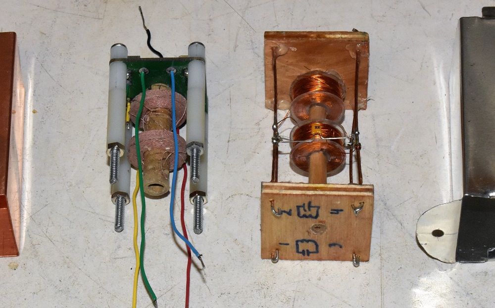
Both Ed and Bill have sent me samples of their work. Bill's look as if they were wound in a factory with litz wire and a smooth sided pi winding. Ed's look as if they were wound by hand because indeed they were. Bill's came with shield cans made from sheet copper. Ed's came with shield cans made from tin plated sheet steel. I don't want to turn this in to a contest between Ed and Bill but it seems inevitable that the reader will interpret it that way.
Here is a picture of the two I F transformers removed from their shield cans. Bill's on the left and Ed's on the right.
Picture 1, Two Different Homemade IF Transformers. See Text Above.
A necessary step is to measure the Q of the coils at the operating frequency of 455 kHz. That requires disconnecting the trimmer capacitor. The Q meter works by resonating the coil with its own internal capacitor. The external capacitor must be removed. The table below gives values of Q measured with the Boonton 260 Q meter at 455 kHz and values of inductance measured at 250 kHz. Also shown are Q values measured with a DER EE model DE 5000 digital LCR meter at a frequency of 100 kHz with the resonating capacitor connected.
Table 1. Values of Q and Inductance of Bill's I F transformer coils.
Transformer assembly is in open air as shown in photo above.Instrument Coil Frequency
(kHz)Q at
FrequencyL (mH) Resonating
CapacitorQ Meter Plate 455 100 1.54 No Q Meter Grid 455 90 1.52 No DCLR Meter Plate 100 25.6 1.5511 Yes DCLR Meter Grid 100 19.57 1.4087 Yes Next I wanted to measure the inductance and Q of the coils inside the shield can. But Bill had presented me with a problem in this area. He sent me one transformer and two shield cans. One was soldered along the seam while the other was not soldered as shown in the photo below. When I took this picture I had already placed copper foil tape along the seam.

Picture 2, Shows Transformers and Empty Cans Along With Digital RLC Meter.
When it arrived on my bench the transformer was installed inside the unsoldered can and was jammed in so tightly I feared I would damage the transformer assembly while getting it out. I did eventually extract it by expanding the opening at the seam. There was no way the transformer would ever fit into the soldered shield.
My reason for wanting to measure inductance and Q with the coils inside the shields is because the shield causes a change in both of those parameters of a coil. The why is, that the shield is one big shorted turn surrounding the coils. You know what a shorted turn will do to a power transformer. It would have an analogous effect on an I F transformer if coupled too tightly to the coils. That's why I F transformers of this style of construction are always so large. The open seam in the shield would negate the "shorted turn" effect but it would also render the shield next to useless by permitting magnetic fields to enter and leave the shield cans. It was impossible to bring the two sides of the seam into electrical contact with the transformer inside. So I used copper foil tape on the outside and inside of the shield to electrically join it into a single continuous conductor. It was very difficult to disconnect the coils from the resonating capacitors and still make connections to the coils. Consequently the Q meter was not used to measure inductance and Q at 455 kHz with the transformer in the can.
Table 2. Values of Q and Inductance of Bill's I F transformer coils.
Transformer assembly is in the shield can.Instrument Coil Frequency
(kHz)Q at
FrequencyL (mH) Resonating
CapacitorDCLR Meter Plate 100 19.45 1.4868 Yes DCLR Meter Grid 100 17.50 1.3778 Yes Now let's have a look at the frequency response of the transformer. Here is the diagram of the test circuit.

Figure 1 Test circuit for I F transformer.
For a verbal description click here.
Making this diagram work depends on having either a two channel generator or one with a sync output on the back.
If you have a two channel generator set the frequency of the second channel to have the same period as the sweep time set for channel 1. For best results set the wave to square. Connect the second channel output to the external trigger input on the scope and be sure to select it as the trigger source.
If you have a single channel generator but it has a trigger output, connect it to the external trigger input on your scope. Be sure to select it as the trigger source.
If you have a single channel generator that has a trigger input, not a trigger output, you need another function generator. I have seen bare board generators for 10 dollars. Or you could go with the 50 dollar Chinese generator I discuss on my daily log page. Here is how to hook it up.

Figure 2 Alternate Test circuit for I F transformer.
For a verbal description click here.
If you don't have a two channel scope just leave off the channel two connection. If you want to measure the insertion loss you will have to move the scope probe from the secondary to the primary. You will also have to readjust both trimmer capacitors because the probe adds some capacitance. Your goal in adjusting will be to achieve the double humped response as shown as shown by the purple trace in picture 3 below and have the center of the dip occur near the intended center frequency of the transformer. I acknowledge that this will be difficult without being able to see the secondary voltage. Thinking of using an RF voltmeter? Do it ONLY if you can rig up a scope probe to work with it. Also remember to stop the sweep and set the generator to a constant frequency.
The value of the resistor effects the Q of the plate (primary) coil. Picture 3 was taken with a value of 100 k ohms. The primary voltage shows a double humped response because the secondary is taking energy from the primary. This effect is maximum at the resonant frequency of the secondary.

Picture 3, Screenshot Of Oscilloscope Showing Insertion Characteristic Of Bill's Transformer.
For a verbal description click here.
Bill told me that he had read somewhere that Professionally designed I F transformers were made with a higher Q in the plate winding than in the grid winding. At first I was skeptical but after some thought I understood the reasoning behind it. In an operating radio the secondary, (grid winding) has no load except a capacitive one from the grid of the following tube and wiring capacitance. This becomes indistinguishable from the adjustable trimmer which makes up most of the capacitance connected in parallel with the coil. On the other hand the primary, (plate winding) is connected in the plate circuit of a pentode tube. The plate resistance is admittedly high, 250 k and up, mostly the latter, which will tend to lower the Q of the primary coil. Bill designed his transformer in this way and he did the right thing but he over did it a bit. As will be covered below the coils in his design are over coupled which could lead to a double humped response.

Picture 4, Scan Showing Only the Secondary voltage.
For a verbal description click here.
To understand the cursors you probably need a little help. The Y1 cursor is set to the -3 dB point on the curve. The vertical range is set to 700 mV / div. The curve comes up 4 div from the center so the height of the curve is 700 mV/div x 4 div = 2.8 v. -3 dB is 2.8/sqrt(2) = 1.98 V. The Y1 cursor is actually set to 1.95 v but what's 3 hundreds of a volt between friends? The X1 and X2 cursors are set to the -3 dB points on the curve. X1, X2, and ΔX are read out in milliseconds so we must translate them to kHz. The time per division is set to 20 ms/div and the frequency scale is 10 kHz/div. Dividing 10 kHz/div by 20 ms/div causes div to cancel leaving 0.5 kHz/ms. So the ΔX reading of 42.4 ms translates to 21.2 kHz. That's wide enough for high fi sound but too wide for night time D exing.
Coupling, Over, Under, and Just Right.
When two resonant circuits that are tuned to the same frequency are coupled together the band pass they produce depends on the amount of coupling. If they are over coupled the response is a double humped curve as shown by the upper scope picture above. If under coupled the insertion loss goes up but the bandwidth gets narrower. Sometimes loss is tolerated to obtain narrow bandwidth. But when the coupling is just right, as shown by the lower scope picture�ah, that is just right. The amount of insertion loss is minimum and the bandwidth has a nice single humped response. It doesn't matter if the method of coupling is magnetic as is used in tube type I F transformers or capacitive as in the transformers shown on this page. For more details on why over coupling produces the double hump follow this link. At the end of that page you will be given a choice of 3 links. The "Winding Your Own IF Transformers" link will bring you right back here.Adjusting the Coupling.
The equation for critical coupling is;KCRIT = 1/sqrt(Q1 Q2); Where Q1 is the Q of coil 1, Q2 is the Q of coil 2, and KCRIT is the critical value of the coupling factor K. The most obvious way to adjust coupling is to move the coils. But if glue prevents that there is still another way. That is to adjust the value of Q of 1 or both coils. In the top scope picture the resistor that connects from the output of the signal generator to the primary winding is 470 k ohms. In the bottom picture the resistor has been changed to 100 k ohms. As Q is decreased the value of K increases. The original value of K which was too high for the conditions of the top picture becomes just right for the conditions of the bottom picture.
Insertion Loss.
Figure 1 above shows how to measure the insertion loss. The trace that resulted is shown in picture 5 below.

Picture 5, Scope Screen Showing Gain or Loss of an IF Transformer.
For a verbal description click here.
The worst case insertion loss is -1.41 dB taken at the center frequency. That's not bad. The failure of the input voltage to show symmetry around the center frequency is due to the difference in Q between primary and secondary. Although the cursors show an increase of voltage the two points are at two different frequencies which is not correct procedure.
Ed's I F transformer.
Scramble wound instead of pi wound, magnet wire instead of litz wire, Ed's transformer seems to have everything going against it. At least that's what the theory says. Let's do some practical measurements and see what we get.
Table 3. Values of Q and Inductance of Ed's I F transformer coils.
Transformer assembly is in open air as shown in photo above.Instrument Coil Frequency
(kHz)Q at
FrequencyL (mH) Resonating
CapacitorQ Meter 1 & 3 455 9 1.20 No Q Meter 2 & 4 455 10 1.24 No DCLR Meter 1&3 100 30.1 1.1931 Yes DCLR Meter Grid 100 30.0 1.2301 Yes
Table 4. Values of Q and Inductance of Ed's I F transformer coils.
Transformer Assembly is in Shield Can.Instrument Coil Frequency
(kHz)Q at
FrequencyL (mH) Resonating
CapacitorQ Meter 1 & 3 455 8 1.18 No Q Meter 2 & 4 455 8 1.21 No DCLR Meter 1&3 100 23.4 1.1668 Yes DCLR Meter Grid 100 23.1 1.2020 Yes

Picture 6, Sweep Of Ed's Transformer.
For a verbal descriptionclick here
The cursors show a -3 dB bandwidth of 31.6 kHz. At this point I will remind you that Radio engineers use the -6 dB points for specifying bandwidth. In the usual AM broadcast radio there are two if transformers so -3 dB in one transformer adds up to 6 dB in two of them.
insertion Loss.

Picture 7, Insertion Loss Of Ed's Transformer.
For a verbal description click here.
The measurement values near the bottom of the screen can be used for the calculation. The P-P (peak to peak) readout is the maximum value on the screen. From this we have Loss = 20 Log(0.318 V/1.46 V) = -13.24 dB. That's a lot.
Conclusions So Far.
Although the hand wound transformer looked promising on the DCLR meter, when it was read by the Q meter at its operating frequency the results were worse than disappointing. The combination of scramble winding and magnet wire was too much against it and it didn't stand a chance.Some may question how the DLCR meter could read essentially the same Q values at 100 kHz and the Q meter readings be so different at 455 kHz. As a matter of fact I wondered about this myself. To test this I measured the Q of one of Ed's transformers at a series of frequencies moving down to 100 kHz. As a reminder at 455 kHz the Q of the coil connected to terminals 1 and 3 read 8 on the Q meter. On the DCLR meter the Q read 23.4 at 100 kHz.
When I lowered the Q meter frequency to 250 kHz the reading was 13.5.
At 200 kHz the reading was 16,
at 150 Kh0z the Q was 19, and
at 100 kHz the Q meter read 24.
Nuf said?
Those of you who know how a Q meter works will know that I had to connect fixed capacitors to the C terminals of the Q meter to achieve resonance at these low frequencies. I used High Q silver mica capacitors.On the other hand a properly wound coil using litz wire gave a good account of itself. I think the inductance was a little high. A few years ago one of the members of the Fun With Tubes list disassembled the IF transformers from an AA5 and measured the inductance. He found that for the interstage transformer the inductance was about 1 mH and for the output IF transformer, (not to be confused with the audio output transformer), the inductance was about 600 μH.(Note: The output IF transformer couples signal from the last IF amplifier to the detector.)
For those who don't want to go through all the difficulties involved with winding your own coils I recommend using commercially available RF chokes. Their Q is a little on the low side but is sufficient for AM broadcast radio applications. I have used them for many years and they provide selectivity that is good enough with little insertion loss. If you want to make an I F strip for SSB reception you may have to resort to winding your own coils.
Winding Our Own I F Coils.
I was lucky enough to find a complete Morris coil winder on eBay. It turned out to be in pretty good condition. I also ordered, from another seller, 200 feet of litz wire. Bill told me that he had used 5/44 to wind his coils. At this writing I had not found 5/44 anywhere. What I ordered was 10/46. Since that's all there is it will have to do. I got the feeling that I couldn't wind many coils with 200 feet of wire but I was unwilling to put a lot of money into it at this time.Someone on the FWT list raised the question whether using tin plated steel for the shield can was a good, bad, or neutral, idea. Well, let's find out. Ed's coil has such a low Q that it is very difficult to get a good reading of Q. Bill's coils are wound with litz wire and have a much higher Q at 455 kHz. The first step was to get his transformer in shape so I don't have to clip to the end of litz wire to make the measurement. I removed the trimmer capacitors from the PC board and then operated on it with a file until it would fit into the copper can that was soldered along the seam.
Effect of Shield Cans. Shield Material Coil Q @ 455 kHz None * Primary 73 None * Secondary 60 Copper Primary 59 Copper Secondary 58 Tin Plated
SteelPrimary 42 Tin Plated
SteelSecondary 43 * In open air.
Well, there you have it. Ed you were right. The shield forms a shorted turn around the transformer. Copper is a shorted turn with minimum losses. Tin plated steel is a shorted turn but with more losses than copper so it absorbs and dissipates more energy than copper. Super cooled conductors anyone?
The average of several measurements seems to indicate that Bill made his copper shields out of 0.021 inch copper sheet. The cut edges say solid copper. I think you can still get copper flashing to go around roof penetrations. I know it's thinner than that and I'll bet it's copper plated steel.
The coil winder from eBay came with wire guides that didn't look right. One was too short. To wind a usable coil the wire guide must literally ride on the coil as it is being wound. The one in the picture below that has the spring on it is too short to reach the coil. The other one has a hole that is too large to control the fine as sewing thread wire in a repeatable way.

Picture 8. Two Wire Guides That Came With the eBay Winder.
I'm quite sure that these are not the best wire guides. Bill has told me about one that looks like the eye of a needle. What looks more like a needle's eye than a needle's eye? I'll bet few men know they make needles like this. The other item shown is a needle threader. They are made for men who couldn't thread a needle if their lives depended on it. The blind and visually impaired also find them useful. I had to go to Amazon to find them as Hobby Lobby let me down.

Picture 9. Close Up Of Sewing Needle and Needle Threader.
Shown below is an assortment of needles bought at Hobby Lobby. One of them is likely to be the right size for the wire guide at the coil.

Picture 10. Package Of Assorted Needle Sizes.
The Enhanced Coil Winder.
Bill sent me a picture showing how he has set up his coil winder. He apparently has 1 and a half Morris units. Well, thanks to bill and eBay I also now have one and a half units. So I think I'll do something similar.

Picture 11. Enhanced Coil Winder Built By Bill.
I copied his winder and went on to add my own changes and enhancements. The shaft that holds the wire supply spool fits rather tightly into the holes in the two blocks of wood so I put an ordinary knob on one end to make it easier to remove. 1/4 inch steel dowel can be bought at any hardware store worthy of the name. I found a piece of scrap wood in my shop and drilled a 1/4 inch hole across the grain at one end. The fit was rather tight which means I don't have to capture it to keep it from moving on the wire guide shaft. Then I drove a sewing needle into the other end going with the grain. The end of the eye closest to the wood should be even with the axis (center) of the coil shaft.
I ordered two stepper motors and driver modules. The two motors are seen at left rear and right front. One of the driver modules is seen to the left of the plywood base. The two driver modules have since been mounted to the base.
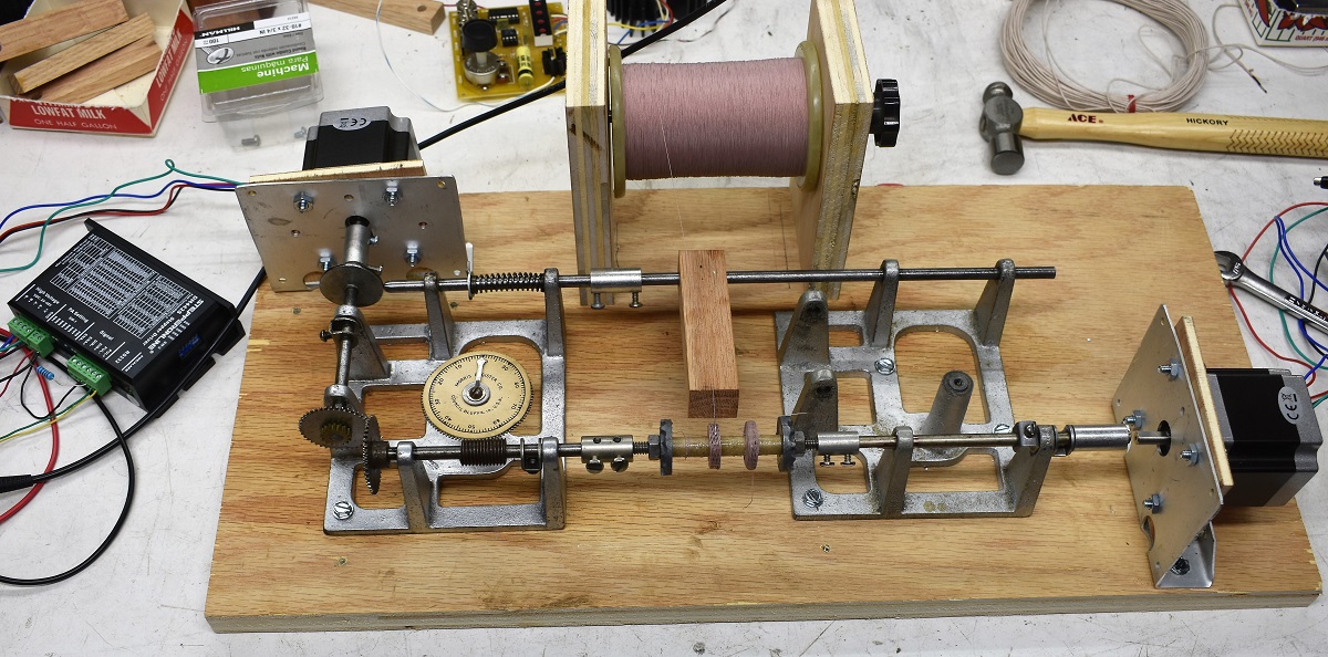
Picture 12. Enhanced Coil Winder I Built.
The reason for having two motors is to be able to run the coil and cam shafts at any speed ratio to permit adjusting the winding spacing. As I understand it closer is better and just touching is best. After I get both drives fully implemented I intend to do some research in this area.
First of all at this time I am using only one motor. You can see clearly that the motor on the right is not coupled to the shaft. The speed ratio is being determined by the gears at the intersection of the two shafts and there are only two choices that are reasonable.

Picture 13. Close Up Of Coil As It Is Being Wound.
The advantage of combining two coil winders into one is that the coil shaft is supported on both sides of the coil. Also the wire guide shaft is supported on both sides. This should make for more precise winding.
Before installing the motors on the plywood base I fired up one of them and a driver board. Control and pulse inputs are optically isolated. The enable input is indicated as positive logic meaning that a high level enables while a low level disables. It didn't work and the red error led was on. After puzzling over it and rechecking for about half an hour I decided to try a low level on the enable input. The red light went out and the motor ran smoothly. I could vary its speed by changing the frequency of my function generator which I was using for the pulses. Anyone wishing to duplicate my efforts should remember the enable input should have been labeled NOT(ENABLE). Picture 13 above shows that the turns that are supposed to be touching are not. There is a wide gap. By counting rotations of the shaft I was able to determine that the gear ratio was 14/13, coil shaft/cam shaft. Although it is hard to see in picture 10 above the gear on the cam shaft is engaged with the smaller gear on the coil shaft. I shifted gears to engage the camshaft gear with the larger gear on the coil shaft. The ratio then was counted as 21/22. It doesn't matter if the camshaft is running slower or faster than the coil shaft. It's the ratio that makes the coils look the way they do.
Making the Tinning Tool.
Litz wire is made up of a number of strands of very fine wire which are insulated from each other by an enamel coding on each strand. The whole thing is wrapped round and round with fine thread. Some sources say it's silk, others say it's nylon, and others say it's cotton. It doesn't seem to matter a whole lot.The thread covering must be removed before anything else can be done. Bill told me that he removed it with his thumbnail. I scraped at it until I wore a notch in my nail. Maybe Bill eats a high iron died and his thumbnail is made of tempered steel. I have returned to the old standby of sandpaper to remove the outer insulation.
Cut a small piece of sandpaper and fold it with the sand on the inside. Grip the end of the wire lightly and pull it between the two sides of the paper. It will take about 8 or 10 passes to get rid of the cloth insulation. Do not try to remove the enamel with the sandpaper. It will melt at soldering temperature.
To tin the ends of the Litz wire effectively you must immerse it in liquid soldering flux and then immerse it in molten solder. Production lines use devices called solder pots that may hold a pound of molten solder. We don't need anywhere that much for our fine litz wire. After several tries I came up with this device which I call a Tinning tool.
Making the Tool.
Cut an approximate 4 inch length of number 18 solid wire and remove most or all of the insulation. At one end bend a circle in the end of the wire. Use the tip ends of your smallest pair of needle nose pliers. Now at the other end bend a slightly larger circle as shown in the picture below.

Picture 14. Making the Tinning Tool, Step 1.
Now form the wire so the smaller circle is below the larger one as shown below. Wrap some bare number 22 wire around the number 18 wire to hold the circles in alignment as shown. See if you can do a neater job than I did.

Picture 15. Making the Tinning Tool, Step 2.
Melt some solder in the cup made up of the two circles. It's not as leaky as you may think. The surface tension of molten solder is sufficient to keep it from leaking through the hole in the bottom of the cup.

Picture 16. Making the Tinning Tool, Step 3.
Now you need a stable platform for the tinning tool. I fastened mine to one corner of my winder base. It is held in place by a number 6 sheet metal screw. (Note: Since it is going into wood why didn't I use a wood screw? Wood screws are usually flat headed and never have threads that extend all the way to the head. Sheet metal screws have large heads designed not to pull through sheet metal and have threads that go all the way up to the head.) Bend the wire up and out so the working end of the tinning tool is level and above the surface of the piece of wood you have mounted it to. The fine litz wire is easier to see against a dark background so I glued a piece of black plastic beneath it.
The other two objects are caps from Nestle's Pure Life water bottles. These are also glued to the wood. These hold a small amount of soldering flux so I could test two different kinds. This will be explained following the instructions for using the tinning tool.

Picture 17
Tinning the End of the Litz Wire.
Litz wire is made up of a number of strands of very fine wire which are insulated from each other by an enamel coding on each strand. The whole thing is wrapped round and round with fine thread. This thread covering must be removed before anything else can be done.
- Cut a small piece of sandpaper and fold it with the sand on the inside. Grip the end of the wire lightly and pull it between the two sides of the paper. It takes from 6 to 10 passes to get rid of the cloth insulation. Do not try to remove the enamel with the sandpaper. It will melt at soldering temperature.
- Melt a small amount of new solder into the tinning tool.
- Lay the end of the wire flat in the bottle cap to coat the end.
- Position the end of the litz wire across the tinning tool.
- Position the soldering iron at approximate right angles to the wire and above it.
- Lower the iron trapping the wire between the iron and tinning tool.
- The solder in the tinning tool will quickly melt.
- Slowly pull the wire out from between the iron tip and the tinning tool. The idea is to keep the wire immersed in the reservoir of molten solder so the individual strands will be coated with solder.
Like any manual procedure this takes practice. You probably won't get it right on the first try.
The soldering flux.
You will need soldering flux to make tinning the ends of the wire easier. If for some reason you don't buy either one of the products discussed below, read the label or webpage description carefully. YOU DON'T WANT ANYTHING THAT CONTAINS ACID!

Picture 18
Containers of the two kinds of flux I tested are shown above. The one on the left is from Kester, which is a well known and respected name in soldering supplies. The product name and number are TEKLINE 959T.
It's odor is the same as drugstore alcohol. As you might expect it evaporates rather quickly. That is why I placed the flux containers very close to the tinning tool. When using this type of flux you need to have your soldering iron in hand, dip the wire in the flux and go right to the tinning process. Although this product is environmentally friendly it doesn't do a very good job of fluxing the wire. Sometimes it takes me 2 or 3 tries to get the end of the wire tinned. .
The one on the right is the traditional rosin flux. It has a stronger odor and doesn't evaporate nearly as fast. But it is the stickiest substance I have ever encountered this side of super glue. I got some on my hands and the sensation was close to the first time I used super glue and like many first time users glued my thumb and forefinger together. Not only that, when I went to wash my hands I found that soap and water wouldn't even scare it. I had to wash with some of the afore mentioned drug store alcohol. As you might have guessed spills are tough to clean up.
It does stay on the wire after dipping and gives a satisfying sizzle and puff of smoke upon contact with the soldering iron tip. It also quickly and completely coats the strands with solder thus holding them together. This is the one I recommend with the following precautions. Don't get it on your hands or clothing, and don't spill it on your workbench.
Sewing Bobbins.
The procedure of winding two coils on a cardboard tube with the coil spacing determined by guess and by gosh, is not calculated to produce satisfactory IF transformers. After borrowing sewing needles from the ladies we are going to borrow bobbins. They are intended to hold thread in a sewing machine. While not the perfect size they will do as coil bobbins which will permit adjustment of coil spacing after the coils have been wound. Plastic bobbins come in a blister pack of 10 for $3.99 as shown below.
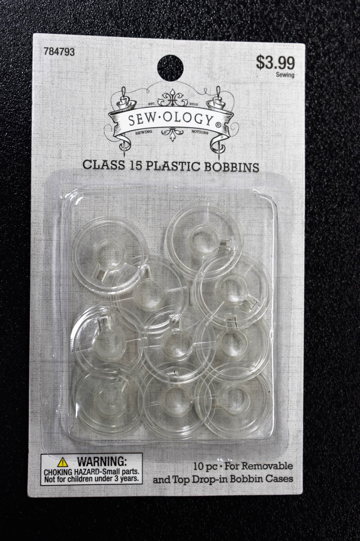
Picture 19
The bobbins protect the coil from handling abuse and provide captive points for the coil wire to exit preventing accidental unwinding of the last turn or turns. If you look back at Picture 13 you will see that the coil on the right has been deformed as a result of being pushed, pulled, squeezed, and otherwise messed with. Two bobbins are pictured below. The one on the left, (two of each kind are shown to give two different views), is the one you want. The one on the right is the one you don't want. The hole in the center is too small to fit over a 1/4 inch rod. The IF transformer will be made by sliding the bobbins over 1/4 inch plastic rod. These will not fit the coil winder or the finished transformer. I experimented with drilling out the center hole and enlarging the small holes on the sides to 1/8 inch. This could be done as a desperation measure but I am going to insist on the kind on the left.

Picture 20
The only place I have been able to find the right one is at Hobby Lobby. I have looked up bobbins on Amazon but the pictures aren't clear enough to be sure that the holes are the right shape. The small rectangular hole in each side is important. Be sure what you buy has them.
To date I have wound 12 coils on bobbins.

Picture 21
Picture 21 shows all the coils I have wound on bobbins to date. The one empty bobbin serves to demark the last four which were doped with Crystal Clear Gorilla Glue. These coils were made for the purpose of testing a product known as Q Dope against rubber cement and Gorilla Glue. Q Dope gives off some quite noxious fumes and I would rather not use it. The Q of a coil treated with it is no better than those treated with rubber cement. As a matter of fact it is a little worse but with a sample size of one coil, it is impossible to draw any definitive conclusions. Those treated with Crystal Clear Gorilla Glue came out better than with rubber cement or Q Dope. Results are summarized in the table below.
Table 2, Q, Inductance, and Resonating C. Measured at 790 kHz. Measured at 455 kHz. Coil # Q L (mH) Q Cr (pF) L (mH)
CalculatedDoped With. 1 97 0.92 83 147 0.832 Rubber Cement. 2 80 0.93 82 149 0.821 Q Dope. 3 99 0.860 82 148 0.827 Rubber Cement. 4 104 0.915 83 146 0.838 Rubber Cement. 5 99 0.94 84 144 0.850 Rubber Cement. 6 105 0.925 84 140 0.874 Rubber Cement. 7 98 0.98 81 140 0.874 Rubber Cement. 8 88 0.915 71 149 0.821 * Wrong Bobbin. 9 103 0.905 84 148 0.827 CCGG. 10 95 0.905 82 146 0.838 CCGG. 11 94 0.950 84 146 0.838 CCGG. 12 94 0.920 83 146 0.838 CCGG. CCGG = Crystal Clear Gorilla Glue.
* Doped with CCGG. Sue brought home the wrong kind of bobbins. I decided to use one to see how it would go. It did not go well. Both the center hole and the wire in and out holes had to be drilled out.
The only column in the table above that needs a little explanation is "L (mH) Calculated" under the "Measured at 455 kHz". The inductance was calculated for each measurement from the formula
L = 1/(4pi2f2C) Where L is the inductance in henries, f is the frequency in hertz, and C is the reading of the capacitance dial in pico farads. The seeming discrepancy between the inductance values at 790 and 455 kHz is easily explained by the self capacitance of the coil which makes the inductance appear larger when measured close to the self resonance frequency.
Q Dope is not pleasant to use which is why I did only one coil with it. Rubber cement is, well, rubber cement. Crystal clear Gorilla Glue is a new product and the reader may not be familiar with it. It has almost no odor at all. When rubbed between thumb and for finger it has a greasy feel. There is not the slightest indication that it wants to glue fingers together. The surface feels tacky for about two hours after being applied. After drying overnight the surface feels hard and dry. When applied to a coil it wicks in as quickly as Q Dope and leaves the individual turns clearly visible. The treated part of the coil looks a little darker than the untreated part.
I think there won't be many readers of this article who will go on to wind their own coils in this way. To duplicate my project you need two Morris coil winders. I was given one which was missing the wire guide. I found another one on eBay that looks like it was put together out of parts from a number of units. Nonetheless I had a good collection of parts and enough ingenuity to repurpose some common items and make a working coil winder.
Some may call me lazy for motorizing the coil winder but I think it is a valid modification that others who already possess a winder may want to duplicate. With the motor providing the power I have both hands free to apply drag to the wire if necessary and watch the progress to be sure all is going well. That's a far cry from turning the crank with one hand, holding the winder from sliding around on the bench with the other and applying drag on the wire with the other. Wait a minute. Did I just run out of hands? Aside from that I used a stepper motor and bought the controller instead of trying to build it myself. That means that the motor can be run at a fraction of its maximum speed and still run as smoothly as a geared down motor. I have been running it at 1 revolution per second. Which means it takes 5 minutes to wind a 300 turn coil.
Captain Kirk to Scotty. "You in a hurry mister Scott?"
An absolutely constant winding speed has got to lead to more uniform coils. The cost of two motors and two controller boards plus shipping from China was a little over $100. Although lots of websites say they have stepper motors most of them don't give torque specifications so you can't be sure you are getting a motor that will do the job.
The reason for two motors is my plan to run the coil shaft from one motor and the cam shaft from the other. By controlling the motor speeds with an Arduino I can set any gear ratio I want. If you don't want to go that far you can motorize your existing winder for half the cost. For now I am operating one motor and using the gear ratio, about 22 to 21, provided by mister Morris.
The Wire Guide.
The wooden part of the wire guide was cut from a 3/4 inch thick board I bought at the home center. If you are not a woodworker you will think it is strange that a board that is 3 and 1/2 by 3/4 inches is called a 1 by 4. Since you need such a small piece you should try going to a lumber yard and ask to look through their scraps. They may charge a nominal fee or they may just give you a small piece.Drill a 1/4 inch hole through one end as shown in Picture 10.
Select a needle with an eye that is just large enough to allow the litz wire to slip smoothly through it.
Drive this needle into the end grain of the wooden piece in the center, up and down, and left to right. Position the bottom end of the eye over the center of the coil shaft.
Be sure the needle is rotated so the wire will feed vertically through the eye. Refer to picture 22.Coil Winding Procedure.

Picture 22
- Every bobbin I have seen so far has sharp protrusions left by the place where the liquid plastic was injected into the mold. I'm not sure how this affects thread but I don't think it's conducive to winding good coils. Use a small file to remove the point. Don't worry about the mold marks caused by the seam in the mold. They don't appear to cause trouble.
- Mount the bobbin on your coil winder with no wire running to it.
- Note: Even if you are going to dope your coil with CCGG you must use rubber cement in the following steps.
- Move the wire guide out of the way and set the winder in motion at about 60 RPM.
- Open your bottle of rubber cement and remove excess cement from the brush in the usual way.
- Apply the brush to the hub of the bobbin on the top or bottom whichever is moving away from you.
- Apply an even coating of rubber cement to the bobbin hub.
- Leave the winder running for a few minutes to prevent the cement from flowing to one side. Blowing on the bobbin while it is turning will help it to dry faster. You should wait until the rubber cement is dry but still has a tacky feel -- about ten to fifteen minutes.
- With the winder still running lower the wire guide bringing it close to the bobbin. Adjust it by moving the wooden piece on the shaft until its side to side movement is within the limits of the bobbin.
- Perform a fine adjustment on the wooden piece until the movement of the needle is centered in the bobbin.
- Stop the motor when the wire guide (needle) is exactly at its left most excursion. To get it exactly right you may have to turn off the power to the motor drive so you can turn the shaft by hand.
- Now thread the needle.
- Loosen the nut on the left and run it far enough away from the bobbin to permit threading the wire through the hole on the left side. Pass it from inside to outside. Pull about 4 or 5 inches of wire through the hole.
- Push the bobbin against the jammed nuts on the right and bring the left fender washer against the bobbin.
- Position the hole at the top and make sure the wire passes through the hole as close to the hub as possible.
- Hold the bobbin and wire in place and run the nut against the washer. Tighten it finger tight, enough to keep it from slipping but not so much as to break the bobbin.
- Wind the free end of the wire around the threaded shaft opposite to the direction it rotates.
- Move the wire guide down against the hub of the bobbin. Take up all slack.
- My roll of wire is heavy enough that it provides all the drag necessary. Yours may not. If not you will have to hold the wire between finger and thumb to put sufficient tension in the wire to keep the coil from falling apart.
- SET THE TURNS COUNTER TO ZERO.
- Start the motor.
- Keep up with the turns counter so you know which century you are in.
- The coils I wound had 270 turns.
- Stop the motor about two turns short of your target value.
- Reduce the frequency of the pulse that is fed to the drive. Run the motor in short bursts to achieve the following.
- You want the wire guide to be as close to the center of the coil as possible when the counter reads the target value, 270 turns in my case.
- DO NOT SLACK OFF THE WIRE.
- Place a drop of CCGG (crystal clear Gorilla Glue) on the coil just in front of the end of the needle. Do not glue the needle to the coil. Allow it to dry for at least 4 hours before removing it from the winder. Overnight is better.
- Next morning gently lift the end of the wire guide while making sure the wire is slack. Push it all the way to the supply roll.
- Cut the wire about half way between the guide and the coil. This way you won't have to thread the needle for the next coil.
- Disassemble the coil holder and retrieve the bobbin with the coil wound on it.
- Thread the end of the wire that comes off the outside of the coil through the hole in the other side of the bobbin.
- Apply a few more drops of CCGG onto the coil where you didn't already apply glue. Give special attention to the place where the wire comes from the last turn. If you get too much glue in a particular place use your finger to spread it around the coil.
- Allow it to dry for at least 24 hours before making any electrical measurements on the coil.
Tinning the Ends of the Wire.
The instructions for tinning which were given earlier are repeated here for your convenience.
- Cut the leads of the coil to a length of 3/4 inch.
- Cut a small piece of sandpaper and fold it with the sand on the inside. Grip the end of the wire lightly and pull it between the two sides of the paper. It takes from 6 to 10 passes to get rid of the cloth insulation. Do not try to remove the enamel with the sandpaper. It will melt at soldering temperature.
- Melt a small amount of new solder into the tinning tool.
- Lay the end of the wire flat in the bottle cap to coat the end with flux.
- Position the end of the litz wire across the tinning tool.
- Position the soldering iron at approximately a right angle to the wire and above it.
- Lower the iron trapping the wire between the iron and tinning tool.
- The solder in the tinning tool will quickly melt.
- Slowly pull the wire out from between the iron tip and the tinning tool. The idea is to keep the wire immersed in the reservoir of molten solder so the individual strands will be coated with solder.

Picture 23
Stay Tuned.