-
R/C
Model airplane
page_  |
| _________________________________________________________________________________________________________
BUI
BINH THO MD
__- |
|
|
|
R/C Model airplane
page
The
British & McDonnell Douglas AV-9M
Sea Harrier II ( version 2025-2045 )
Dr
BUI
BINH THO
|
|
Create : 2018 - new update 23 September 2024 |
 |
|
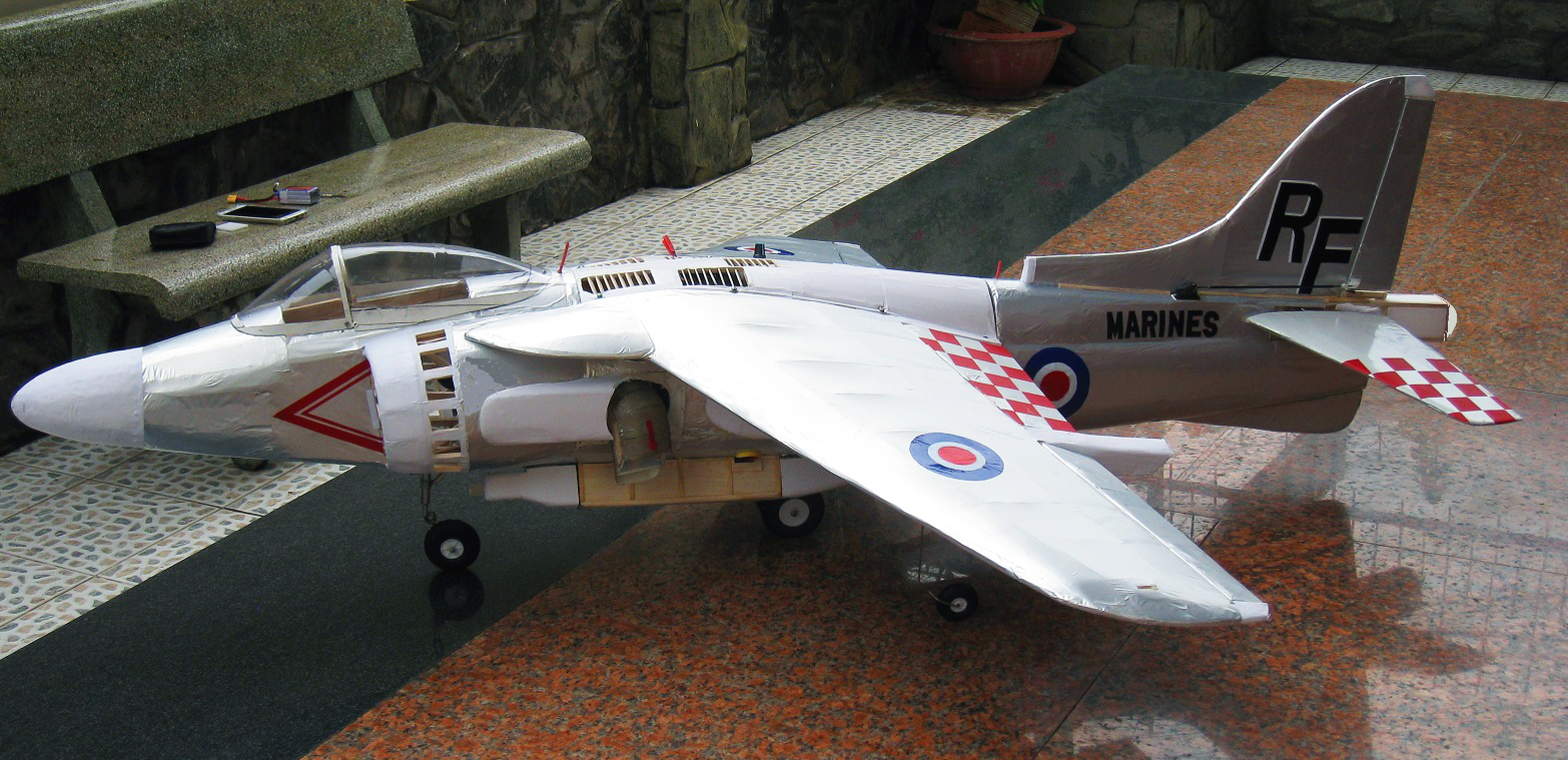
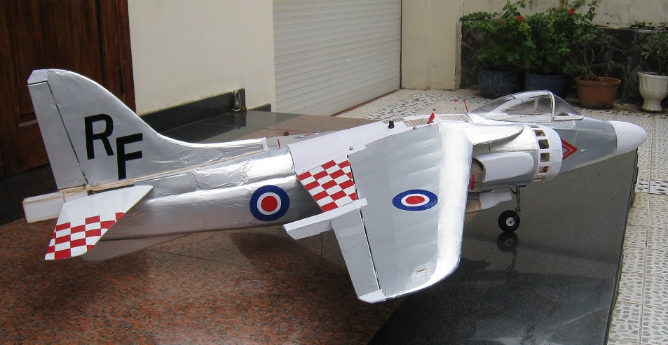
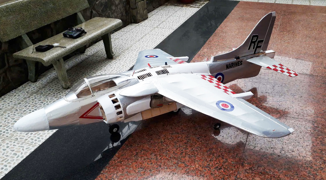
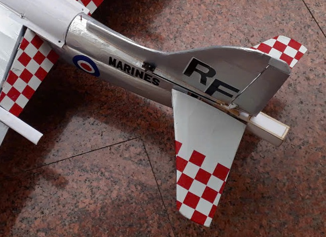
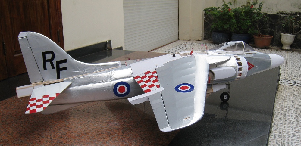
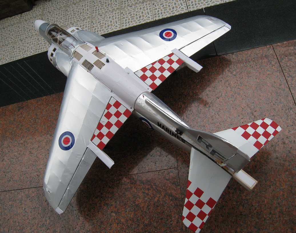
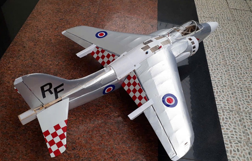
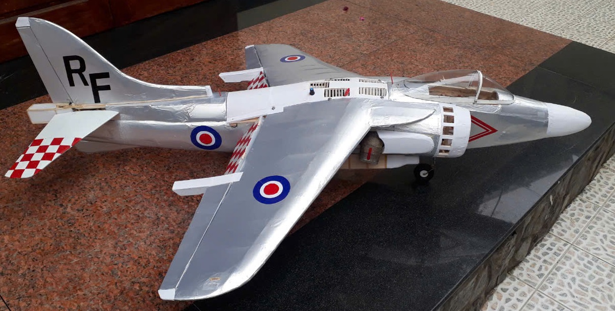
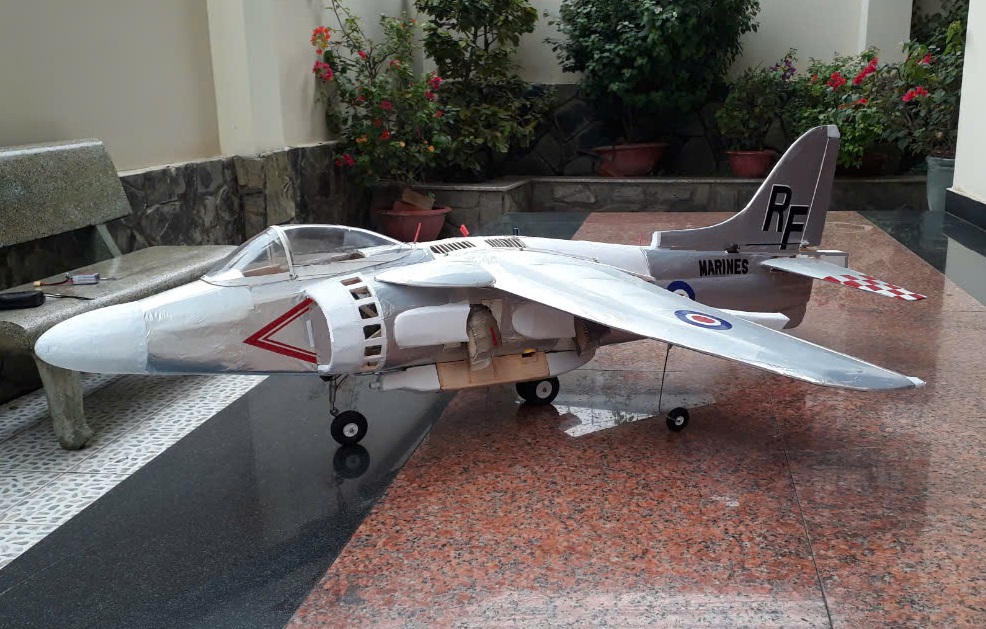
My British & McDonnell
Douglas AV-9B Sea Harrier II
| Wingspan
: 50 inch ( 1260mm ) |
| Length
: 66 inch ( 1680mm ) |
|
High wing air foil NACA 3310.. |
|
Weight : 6.4 lbs |
| Engine :Two ducted
fan : One is 90mm12 balde fan with brushless motor DC 2200W
and Ducted fan 70mm 1200W BDLD motor . ESC 100A
and 120A |
| Contruction :
All wood air frame renforced by 5mm Depron hard foam & thin layer
silver solar film covered . |
| Radio : 2
receiver , 6 channel each |
|
|
|
This the
second time I had build and VTOL jet R/C airplane was the last powered by
ducted fan electric brushless DC engine .The origine airfoil of the
Sea Harrier is 3310 , the dehydral angle are
- 8 degrees .I decide
the NACA of this airplane was as same 3310 . . More light , strong material had
been used to contruct
this model airplane ;but the balsa wood is usually the good materiel to
made it. The contructions of this aiplane all are balsa wooden
air-frame renforced by 5mm Depron hard foam ; covered by thin alumium solar film . The gears
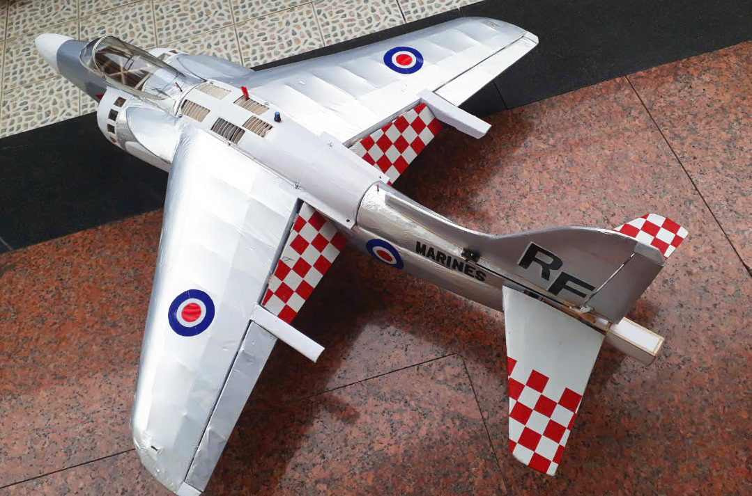
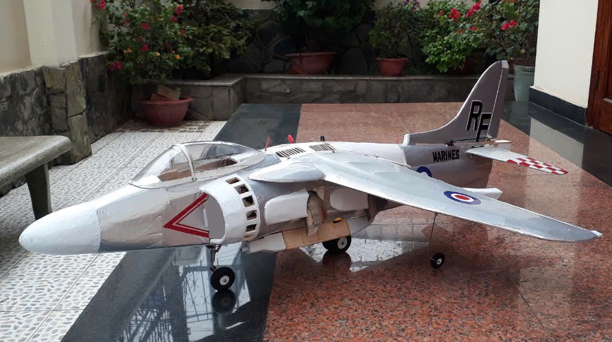
system ( see on the pic ) are quadricyclic , fixed ,
dirigeable and sprintable ( sea pic )
| |
 |
|
 |
|
| |
|
|
|
|
Wing : This is a 1005 square inch aircraft wing
made entirely of balsawood. The wing uses the NACA 3310 airfoil
with a shape and sweep angle similar to the AV 8B, but with
slight modifications to the wingspan, sweep angle, and
surface area (see figure). The two aileron system (see
figure) is independent, with each aileron controlled by a
2.5 kg/cm² servo, hidden inside the wing. The hinges of the
aileron and flap consist of four plastic pieces and are
installed at the middle of the rear wing bar. Multiple holes
in the wing's lamina have reduced the overall weight of the
wing. The flaps are independent and controlled by two 2.5 kg
servos, capable of reaching a 45-degree downward position.
The entire wing is covered with aluminum-colored solar
film |
|
|
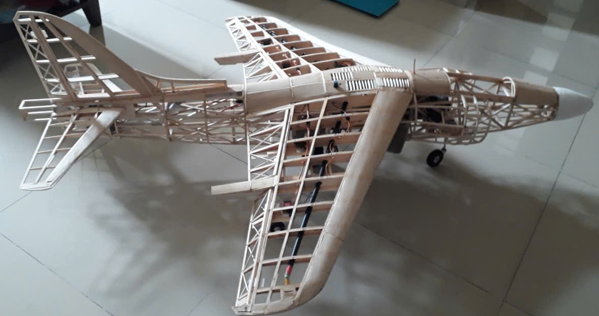
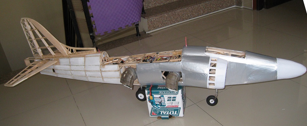
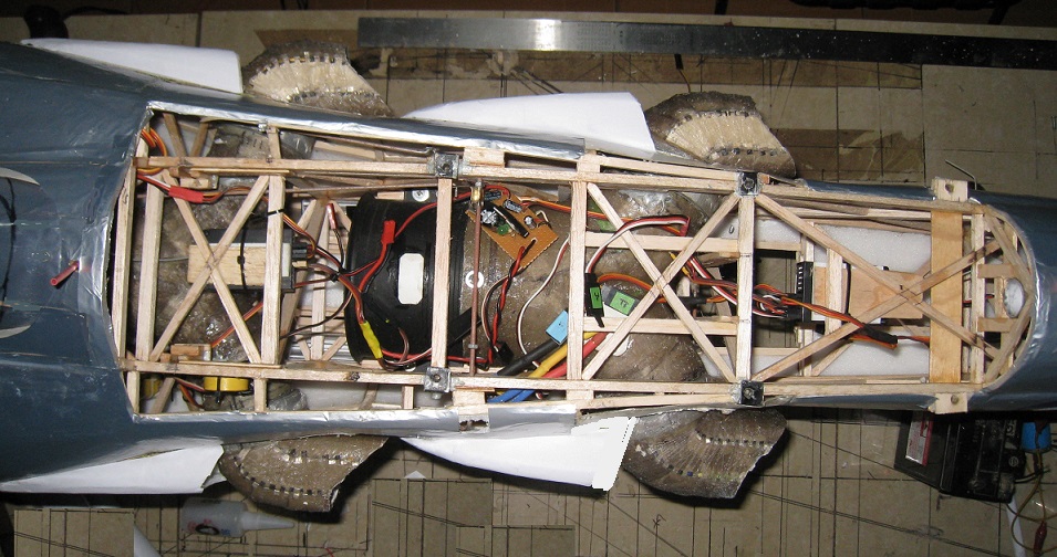
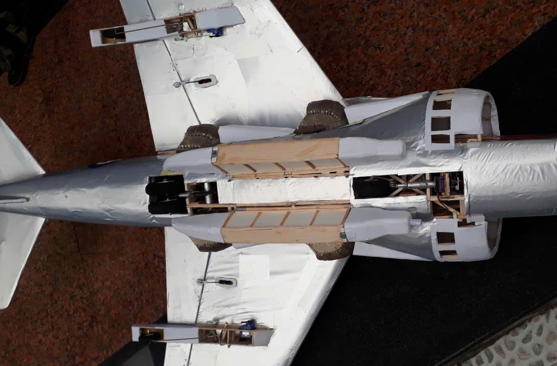
| Fuselage :The main
structure of the fuselage is an entirely wooden frame with four
main 6x8x1200 balsa hardwood beams reinforced with multiple
4x6mm wooden perpendicular and diagonal braces (see figure), and
the fuselage is reinforced with 5mm depron sheet covering.
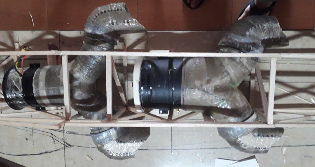
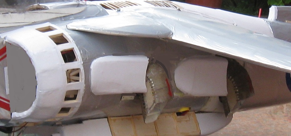
Inside the fuselage are two ducted fans: a 90mm fan with two
dirigeable exhaust ducts, installed at the rear of the fuselage
near the CG (center of gravity), and a 70mm fan installed
towards the front of the fuselage, further away from the CG. The
ducted fan bases and motors are secured to the fuselage with
four long threaded screws. The outer layer is made and covered
by thin layer silver solar film to form the AV 9M
fuselage. The wings are attached to the fuselage with eight 4mm
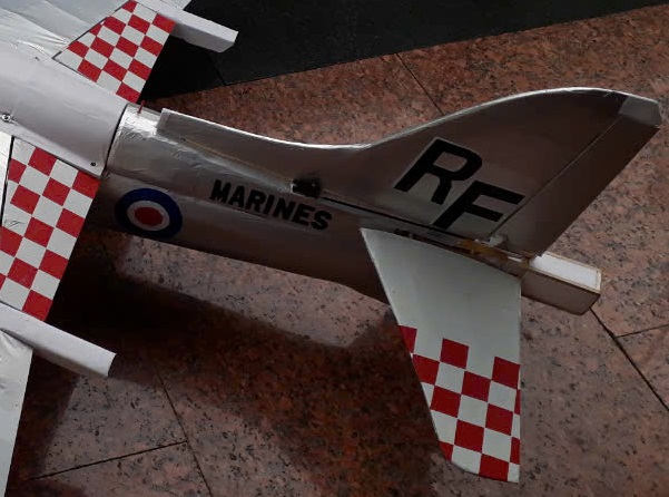
screws. The rudder is larger than the original rudder and is
firmly attached to the fuselage |
|
|
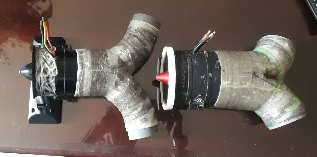
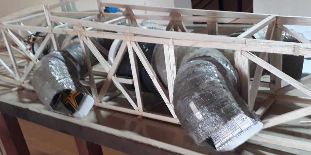
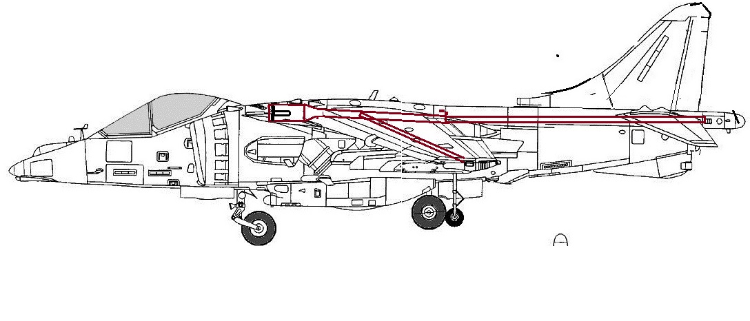
| The ducted fan , motor and
conduct exhaught dirigable pipe :
I use 90 mm ducted fan powered by one 2300W motor and
one 70mm ducted fan with brushless 1600w DC motor, ESC in
use are 120 and 100A with BEC 5v . The conduct pipe is forme by hard
0,2mm paper in form Y and reinforced by two layer fiberglass
compopsite ( sea pic ) .
An servos 13kg intalled to dirigeable syncronized the four
exhaust
pipe ( sea pic ) Two cell 3000mAh 45C Lipopolymer battery are intall
parallelic under the fuselage inbox in 30mm cannon box under the
fuselage .
Gear system : This is a sprintable and retractable
quadricycle gear : all contruction
are steel rod and aluminium tube ( see pic ) and this is the lightest
sprintable gear i had made ( see pic ) . The nose gear was
dirigable by an mini 1,5kg servos
R/C system , servo & other link installation :
Six 2,5kg mini servo for elevator , rudder , aileron and flap & one mini servo
for nose gear , two for stabilizer gear under the wing and one
10,5 kg servos for dirigeable exhaust pipe systeme .
. The two receiver
and the ESC are intall
fixed in high of the fuselage and adjust for the CG (
Center of gravity ) at 35%-40% from the front of the wing cross section . The
two receivers
was place on the highest of the fuselage in the pilot copit
and in the fuselage
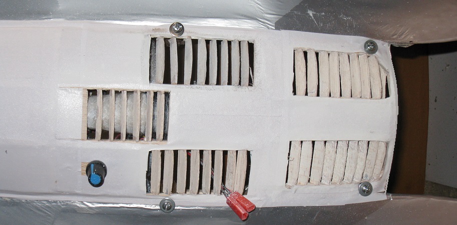
Gyro and hover stabilizer systeme : I use a strong 12V
DC air-cooled mini fan to direct compressed air to the right
, left wingtip, and the rear tube to control the roll,
yaw, and pitch when the aircraft is hovering. An electronic gyro
system is installed to ensure stability when the aircraft hovers
in the air ( sea pic )
|
|
The rudder and elevator's rod are two 2/32 steel wire fixed
at the end ( see pic ) . These are light , hard and had
any trouble in working Rudder , elevator , aileron adjust & flying test : Up
3/4 and down 2/3 inch for elevator . Right 3/4 and lelf 3/4 for
rudder and 1/2 inch for the aileron . On the first fly ,
reduce some on the effect-angle of the aileron an elevator
and slight trim down on elevator ( on the first test flight ).
|
| On a
clear and calm sunday morning , I made my first flying test ...... |
|
Click
to see the
character , it hover and outdoor flying images |
 ___________________Back
to main page ___________________Back
to main page |
|
|
|
-My
home page I My
family home page I My
personal page I Medline
IR/C model airplane page
I Games
I Science
|
|
Add : Dr BUI BINH THO 35B Ho Hoa , To1 , Kp 1 , Tan Phong ,BIEN
HOA , DONG NAI , VIET NAM Email
:
buibinhtho52@gmail.com
Cpyright
© 2001: My homepage's Bui Binh Tho Md
, 35BHo Hoa, to1, Kp1, Tan Phong , BIEN HOA , DONG NAI , VIET NAM . Tel (0251) 8820217 ,
Mobile : 0903358597 . Plus ( +84 ) for all oversea relation .
All
Rights Reserved.
This document is strictly for informational, non-commercial purposes. |
|






 __________________